08/04/2024 13:11:07
Wire Communication Connection from Gateway 3 to Powerwall 3
Warning
Before terminating
any conductors inside Powerwall 3, ensure that the Enable switch
is turned OFF to de-energize the system. Confirm lack of voltage at the AC and PV
terminals before proceeding.
-
Choose one of the following options to run the communication wiring to Gateway 3:
- Use PVC MC cable with integrated communication wiring (enters Gateway 3 via a single knockout)
- Run the communication wiring through the same conduit as the Powerwall 3 AC conductors (enters Gateway 3 via a single knockout)
- Run communication wiring by itself through conduit or cable gland (enters Gateway 3 via its own knockout)
NoteInstaller preference, Utility, and/or AHJ requirements will dictate how communication wiring is run. -
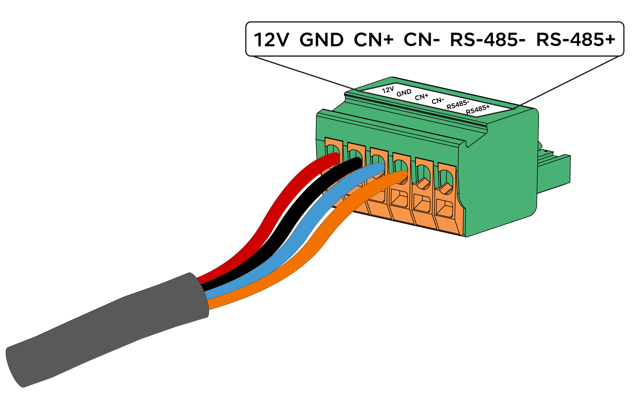
Wire the 4-conductor
communication cable to the Gateway 3 connector:
CAUTIONAlways wire the Gateway 3 connector before plugging it in to Gateway 3. The force exerted to lock each terminal can potentially damage Gateway 3, so wires must be placed and terminals locked before plugging the connector into Gateway 3.
-
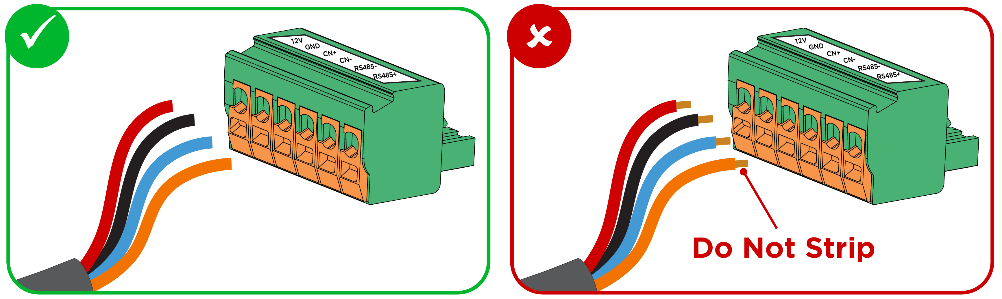
Strip the communication
wire jacket about 3 inches. Do not strip the individual communication
wires.
NoteThe communication connector is insulation displacing, meaning it pierces the insulation of the unstripped wires to make strong electrical contact. Stripping the individual wires may result in wires jamming the connector.
NoteReference Gateway 3 Communication Wiring for the correct wire order in the Gateway 3 connector.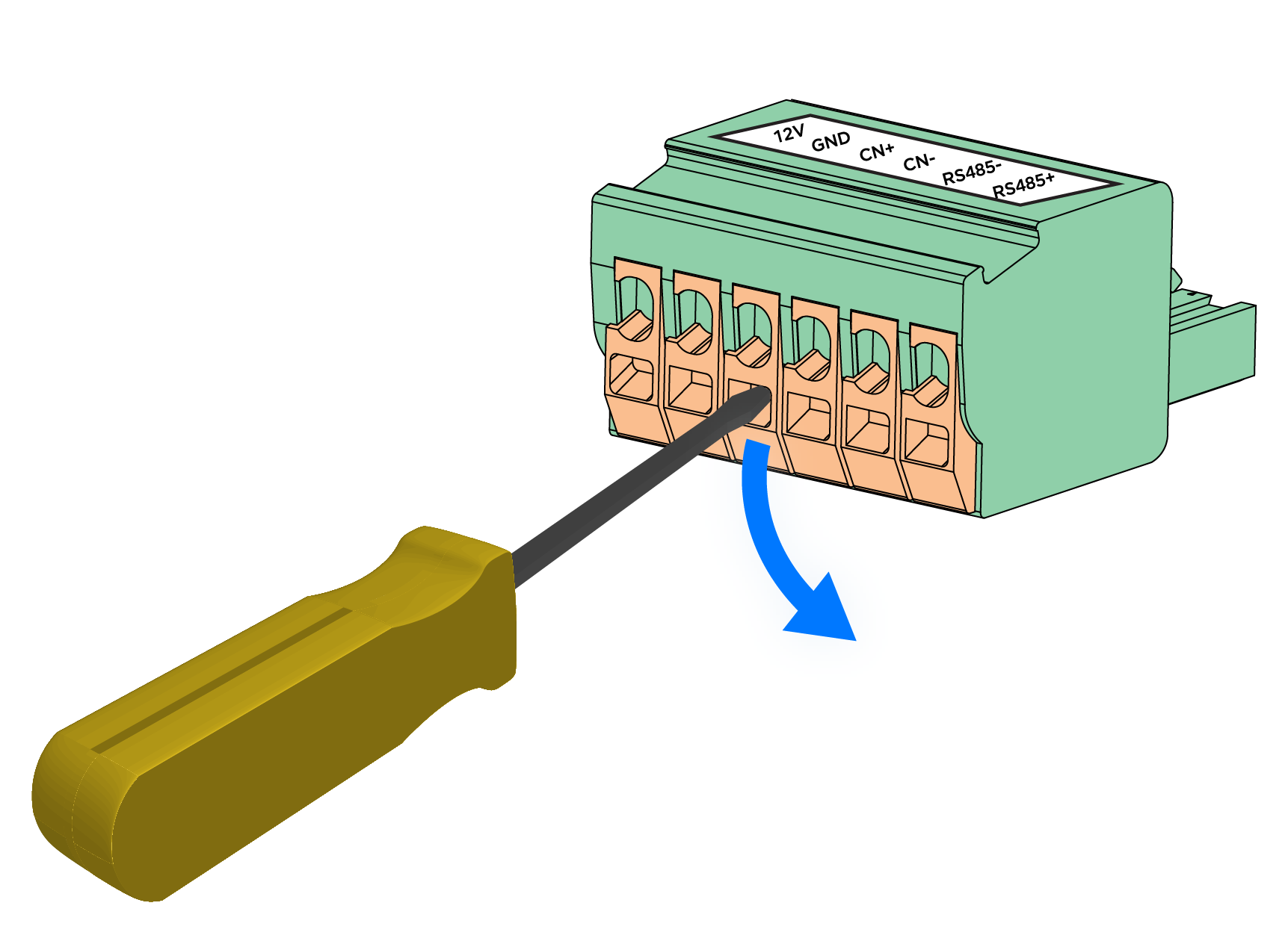
-
Strip the communication
wire jacket about 3 inches. Do not strip the individual communication
wires.
- Plug the connector into the corresponding connector socket labeled "Powerwall" in the Gateway 3.
-
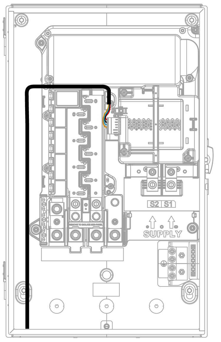
Route the communication cable up
and around the internal panelboard. Do not route the cable across the internal
panelboard, as it could impede door installation.
-
Wire the 4-conductor
communication cable to the Gateway 3 Communication connector in
the Powerwall 3 enclosure:
-
Insert each conductor as
far as possible into the terminal and remove the screwdriver from the
screwdriver slot to close the terminal.
CAUTIONExcessive force may damage the connector; do not apply more force than is necessary to open the terminal and insert the conductor (do not lean on connectors when prying them open).

NoteSee Plan Cable Length Between Components for the maximum distance between components. -
Insert each conductor as
far as possible into the terminal and remove the screwdriver from the
screwdriver slot to close the terminal.