Install Mid-Circuit Interrupters in PV Array
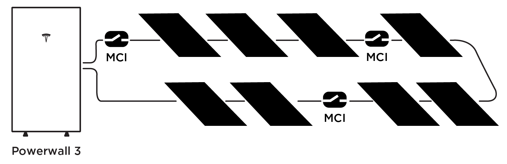
The Tesla Mid-Circuit Interrupter (MCI) is used within PV strings and arrays to meet the Rapid Shutdown requirements of NEC Article 690.12. For information on how the Tesla MCI functions with Powerwall 3 as a Photovoltaic Rapid Shutdown System (PVRSS), see Appendix D: Solar Rapid Shutdown.
MCI Locations
The quantity and placement of MCIs necessary to meet Rapid Shutdown requirements is governed by the UL 3741 (PV Hazard Control System) listing applicable to various array types. The following table lists the systems that have been certified to UL 3741 when installed together with Powerwall 3 and Tesla MCI, and summarizes the required MCI counts and locations to comply with NEC Article 690.12 (B). Refer to the applicable PVHCS datasheets shown in the table for detailed listing and installation instructions to ensure adequate compliance.
| PVHCS System | Module Model | Required MCIs | PVHCS Datasheet |
|---|---|---|---|
| Tesla ZS Systems (ZS Comp, ZS Span, ZS Ramp, ZS Seam) | Tesla TxxxS modules (where xxx = 405 to 450 W, increments of 5) | MCI at one end of string or sub-array, plus 1 MCI per 3 modules1 | ZS PVHCS datasheet |
| Tesla TxxxH modules (where xxx = 395 to 415 W, increments of 5) | |||
Hanwha Q.Peak Duo Flat PV modules:
|
|||
| Tesla Solar Roof | Solar Roof V3 Modules (SR60T1, SR72T1, SR72T2) | MCI at one end of string or sub-array, plus 1 MCI per 10 modules | Solar Roof PVHCS datasheet |
| Tesla Solar Roof V3R | Solar Roof V3R Systems (SR72T3R) | MCI required only at +/- ends of strings, and where strings span mounting planes | Solar Roof V3R PVHCS datasheet |
| IronRidge and Ecofasten Systems | Mounting system and module combinations using IronRidge XR Flush Mount, IronRidge Aire Flush Mount, Ecofasten ClickFit, or Ecofasten RockIt | MCI-1 required only at +/- ends of strings, and where strings span mounting planes | See IronRidge and Ecofasten UL 3741 Addendums for detailed requirements |
| Generic PV Array (Other Modules and Mounting Systems) | Systems using certified PV modules and mounting systems other than those defined above are covered by Tesla's UL 3741 certification if they are in compliance with the PVHCS listing instructions | MCI at one end of string or sub-array, plus 1 MCI every 165 Voc at low design temperature (typically 1 per 3 modules) | Generic PV Array PVHCS datasheet |
Installation Best Practices
- Ensure that Tesla MCIs are not stored prior to installation in environments with moisture or dirt
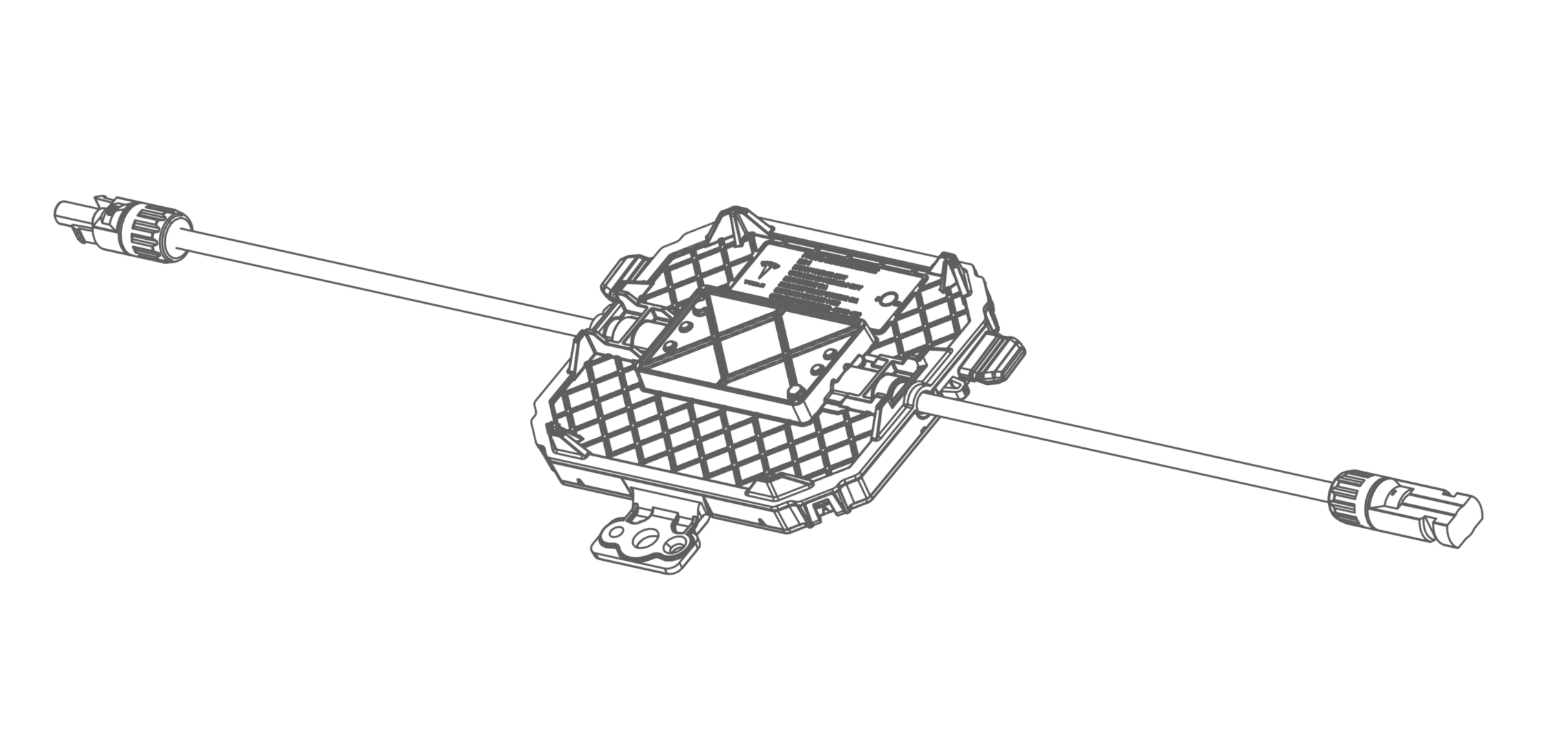
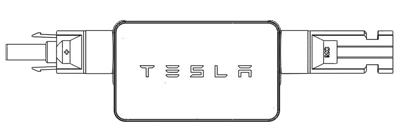
- Install the Tesla MCI in line with the PV modules using standard Staubli Type MC4 certified compatible connectors
- Ensure the MCI is minimum 12.7 mm (1/2 in) from glass or backside of a PV module
- For flat plate solar panel installations, ensure the MCIs do not directly contact the roof. For Solar Roof installations, see the Solar Roof Installation Manual for proper mounting guidance
- For easier servicing of flat plate solar panel installations, install the MCIs on the perimeter of the array if possible
- Always secure the MCI with appropriate wire management
- Ensure no more than 5 MCIs are connected per PV string
- Ensure that total DC circuit
length, from + MPPT terminal to - MPPT terminal (including module wire leads,
jumper wires and all wiring within the array boundary for any individual
string), does not exceed 160 m for single strings or
paralleled strings
- Total DC circuit length refers to the entire round trip wire length, from inverter to the roof, then back to the inverter
- Ensure paralleled strings are the same length, or as close in length as possible (if the paralleled strings are different lengths, it is likely the MCIs will not function properly; this likelihood increases the greater the difference in paralleled string lengths)
- Keep a completed string diagram indicating the layout of the array and the placement of each MCI (either a paper copy, electronic copy available in the field, or both)
Installing MCIs
- Connect the positive and negative
leads of the MCI to the corresponding positive / negative MC4 terminals of the
PV modules or solar roof modules.
- For flat plate solar panel
installations, attach the MCI under the module frame.
- To attach the MCI using
ZEP Home Run wire clips, install the (2X) clips to the module frame and
clip both ends of the MCI leads, then slot the MCI underneath the metal
frame.
Figure 2. MCI-1 Attached with Wire Clips 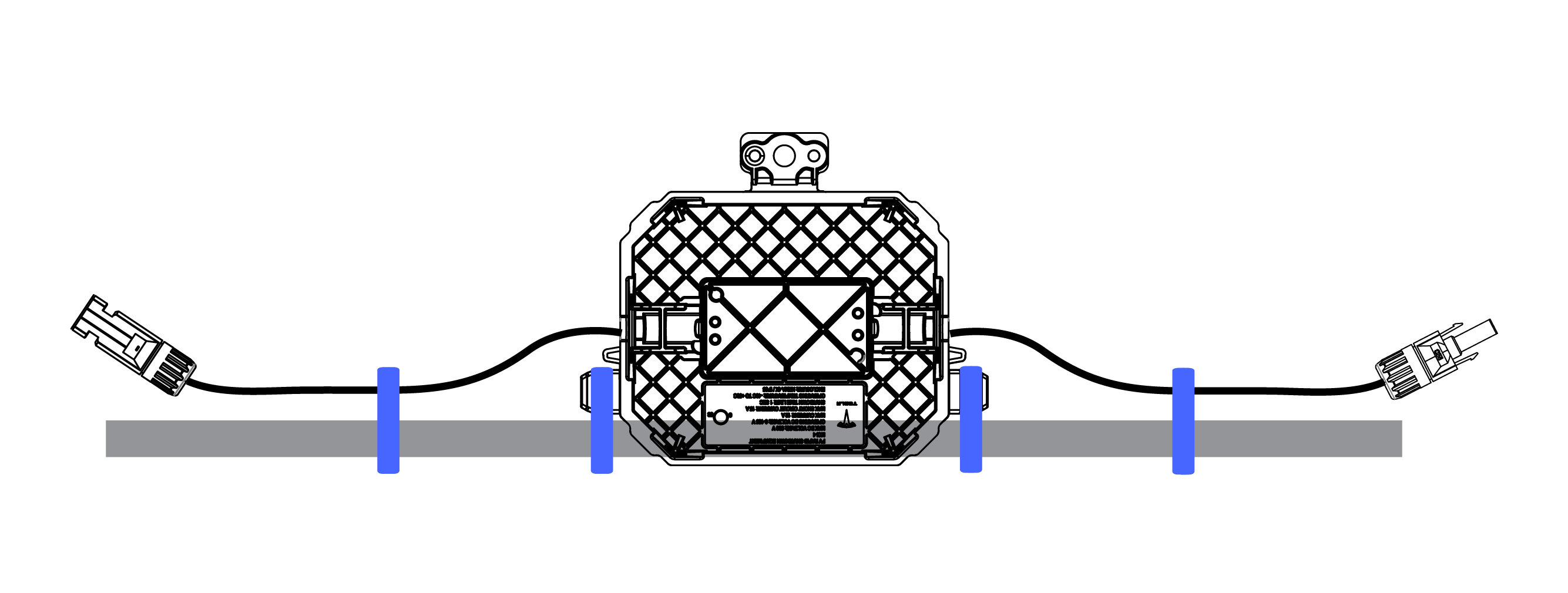
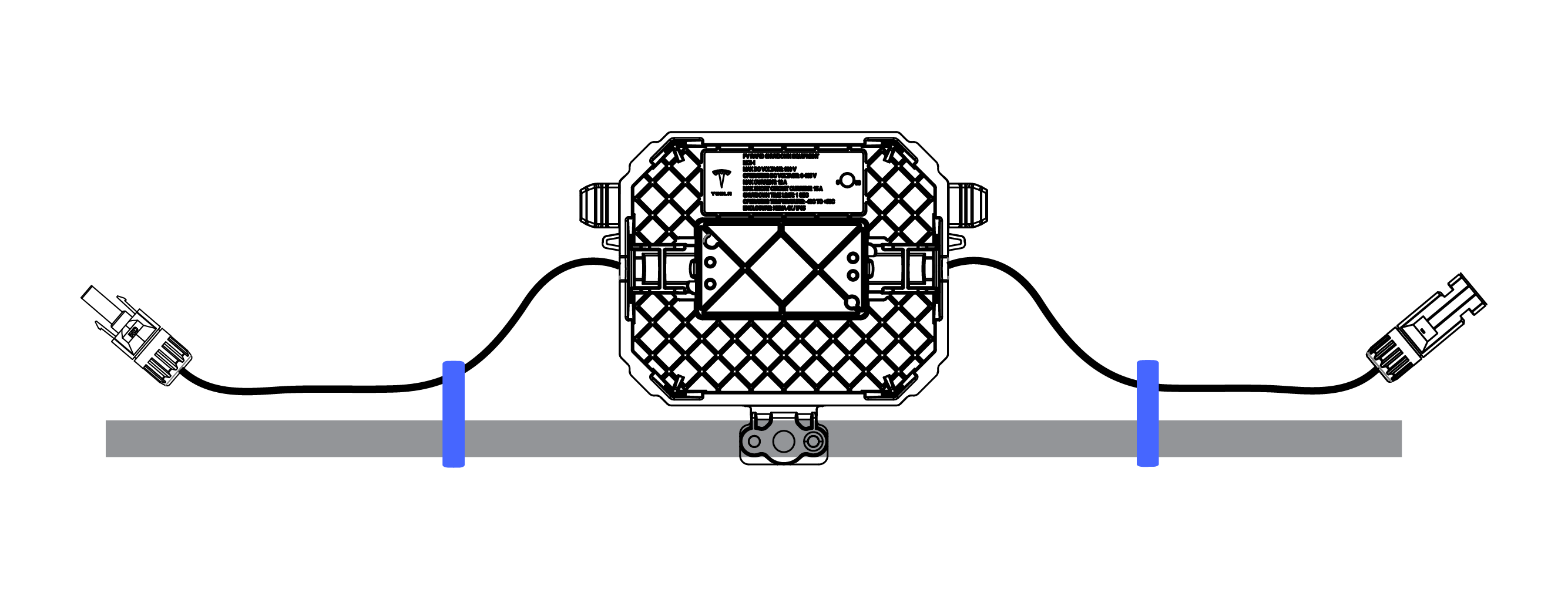
Figure 3. MCI-2 Attached with Wire Clips 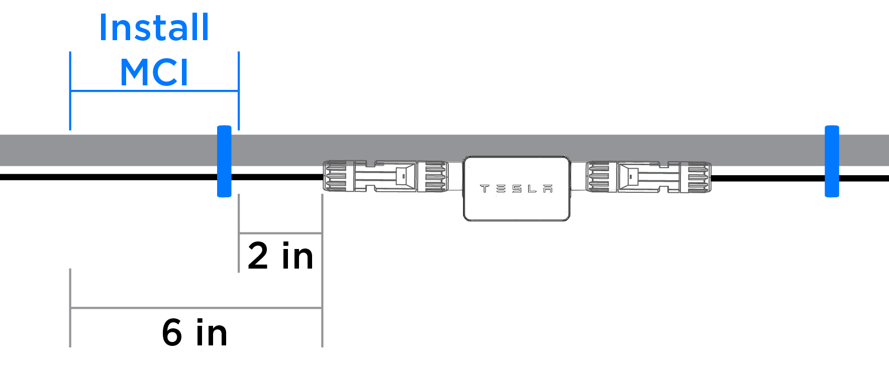 NoteInstall the wire clips at least two inches from the end of the MC4 connector, but no more than six inches from the connector. Ensure the MCI is not directly contacting the roof.CAUTIONDo not twist the MC4 connectors on MCI-2. Twisting the connectors damages the electrical contacts inside, likely resulting in MCI failure.
 - To bolt the MCI to an
existing hole in the frame, align the MCI through hole with the frame
and use the appropriate mounting hardware as defined in MCI Mounting Hardware
Sizing .
 NoteThis option is only available for MCI-1.
- Follow all module manufacturer’s instructions before mounting the MCI to the module frame. Ensure there is at least 0.5 in (13 mm) between the MCI and the module substrate, and only mount the MCI using existing holes in the module frame.
- For rail PV systems, use any of the mounting holes to mount the MCI directly to the rail (see MCI Mounting Hardware Sizing for mounting hardware sizes) or use the manufacturer’s module level power electronic mounting bracket and mount the MCI to the bracket.
- To attach the MCI using
ZEP Home Run wire clips, install the (2X) clips to the module frame and
clip both ends of the MCI leads, then slot the MCI underneath the metal
frame.
- To install MCI-1 on Solar Roof
installations, mount the MCIs directly to the roof, directly above the Tile
Footlaps and positioned at a slight angle as pictured below. Use the appropriate
mounting hardware as defined in the table below.
Figure 4. MCI-1 Installed with Solar Roof Tiles (V3 and earlier generations) 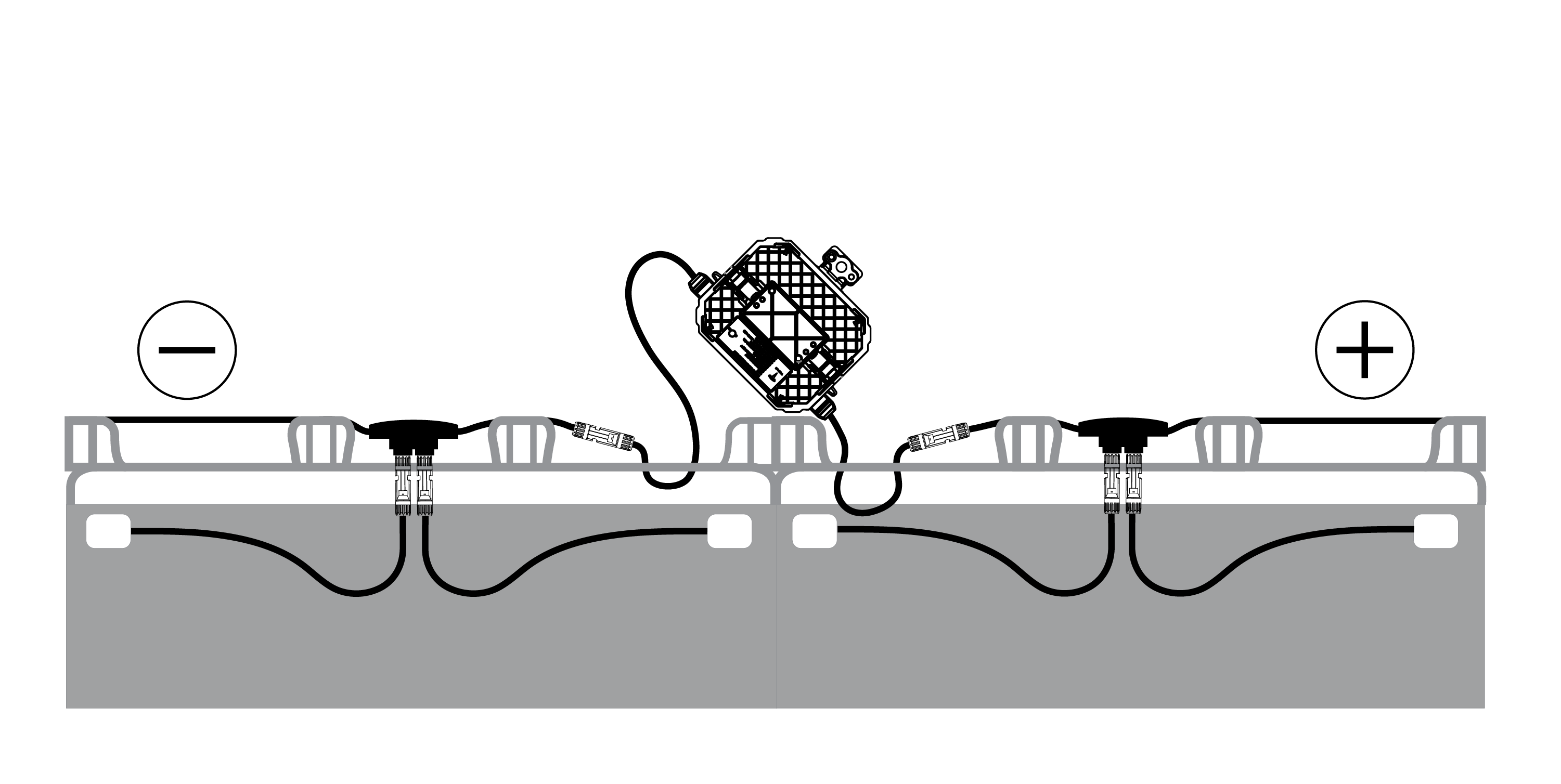
Figure 5. MCI-1 Installed on End of Solar Roof V3R String 
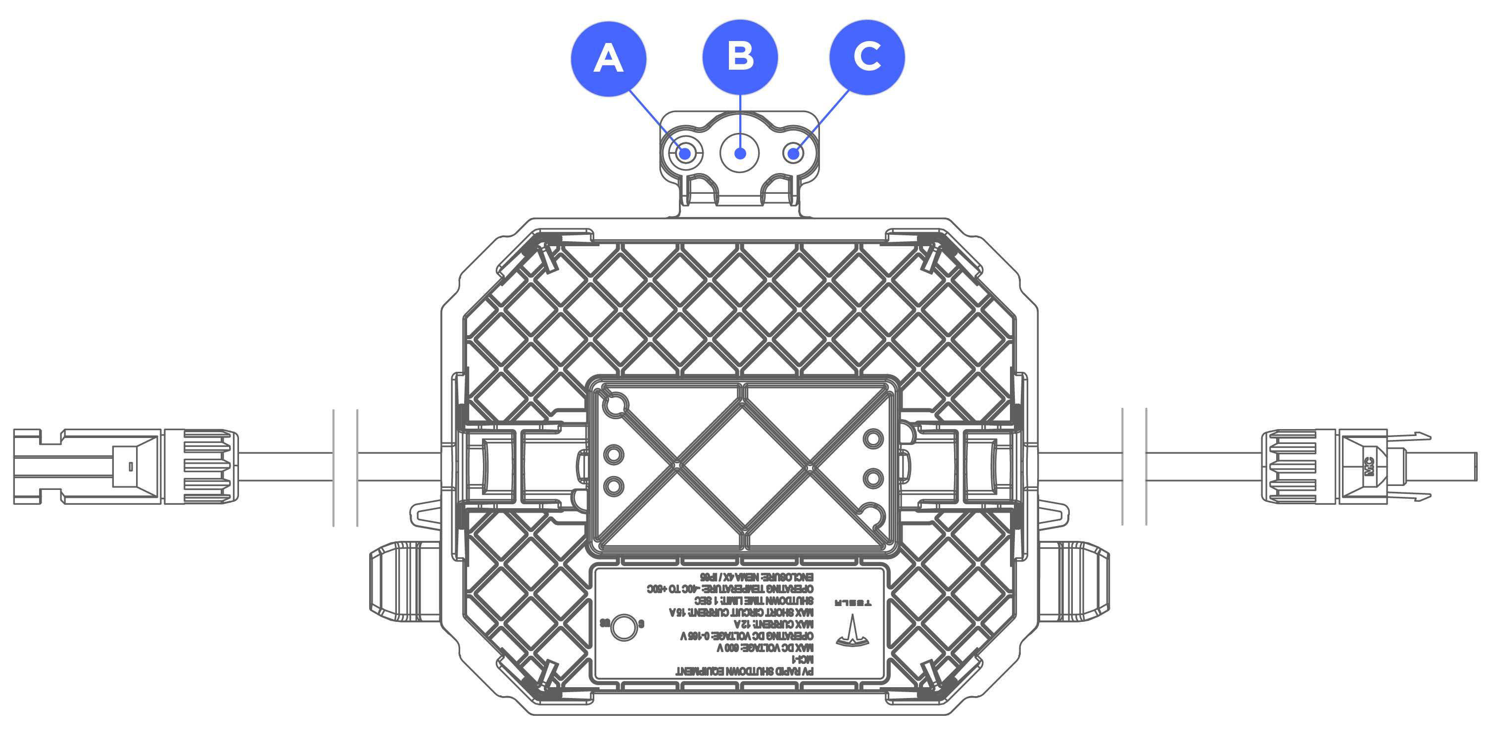
Table 2. MCI Mounting Hardware Sizing Through Hole Hardware A Wood Screw (No. 8) Screw (up to M4 (5/32")) B Bolt (up to M8 (5/16")) C Nail (8D) Screw (up to M4 (5/32")) - To install MCI-2 on Solar Roof
installations, attach each lead of the MCI to the corresponding Staubli MC4
connector, and place an MC4 cap on each of the remaining MC4 connectors. Secure
the cables in the wire management clips.
 CAUTIONDo not twist the MC4 connectors on MCI-2. Twisting the connectors damages the electrical contacts inside, likely resulting in MCI failure.