STEP 8: Install System Shutdown Switch Where Required
Where required by local code, Powerwall 3 can be wired to a remote System Shutdown Switch that manually initiates rapid shutdown, disabling solar output.
The Powerwall 3 On/Off switch is also certified to UL 1741 as a means of manually initiating rapid shutdown. See Appendix D: Solar Rapid Shutdown for more information on the function of both the Enable switch and the System Shutdown Switch.
Install the System Shutdown Switch
Warning
Before terminating any conductors inside Powerwall 3, ensure that the Enable switch is turned OFF to de-energize the system. Confirm
lack of voltage at the AC and PV terminals before proceeding.
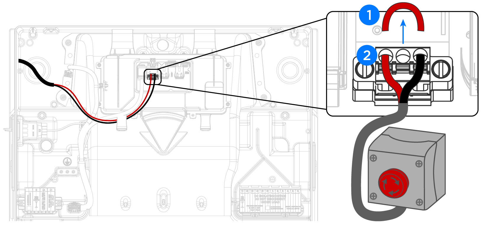
- Remove the factory-installed jumper from the RSD IN / RSD Out ports on the Powerwall 3 RSD connector. See Appendix B: Wiring Reference for a detailed wiring reference.
- Wire the 2-conductor communication wire (minimum 24 AWG conductors) to the RSD ports:
- Strip the communication wire jacket so that it does not extend past the edge of the fan duct. This ensures the individual conductors lie flat, leaving room for the front cover to be installed.
- Strip each conductor 5/16 inch (8 mm).
- Route the two conductors to the connector as shown below, using the wire
management tab to prevent them from blocking the Tesla Asset
Controller.CAUTIONTesla recommends routing the communication wiring into the left side of the enclosure; always use the wire management tabs to ensure wires do not block the Tesla Asset Controller. Do not route loose wires through the front of the enclosure.
- Insert a cabinet tip or electronics tip slotted screwdriver (up to 3/32-inch or 3 mm) into each screwdriver slot to open the terminal.
- Insert each conductor as far as possible into the terminal and remove
the screwdriver from the screwdriver slot to close the terminal.CAUTIONExcessive force may damage the connector; do not apply more force than is necessary to open the terminal and insert the conductor.
- Connect the 2-conductor
communication wire to a suitable DC switch (requirements below).
Switch Requirements
System Shutdown Switches shall meet the following requirements.
- Listed or Recognized as "Emergency Stop Button", "Emergency Stop Device",
"Emergency Stop Unit", meeting one of the following standards:
- UL 508 "Industrial Control Equipment"
- UL 60947-1 "Low-voltage switchgear and control gear- Part 1: General Rules" AND Part 5-1: Control Circuit Devices and Switch Elements - Electromechanical Control Circuit Devices" AND UL 60947-5-5: Mechanical and functional performance requirements
- Normally Closed (NC) switch contacts
- Rated for at least 12 V, 1 A
- Outdoor rated (NEMA 3R or higher)
- Terminals must accept 24 AWG wire or larger
Recommended Switch Components
The following product (composed of all parts listed below) meets all above requirements for this application:
| Emergency Stop Button Option 1: Eaton | Eaton M22-PVT | Emergency Stop Button |
| Eaton M22-I1-PG | Emergency Stop Enclosure | |
| Eaton M22-K01PV6 | Emergency Stop Contactor Block (240V, 6A) | |
| Emergency Stop Button Option 2: Schneider | Schneider XALD01H7 | Emergency Stop Enclosure |
| Schneider ZB5AT84 | Emergency Stop Button | |
| Schneider ZB5AZ009 | Emergency Stop Collar | |
| Schneider ZBE102 | Emergency Stop Contact Block | |
| Schneider ZBZ1605 | Emergency Stop Guard Yellow | |
| Schneider ZBZ1602 | Emergency Stop Guard Black | |
| Low voltage communication wire (Powerwall 3 communication cable preferred) | ||
| ½-inch Strain Relief or equivalent | ||
| (4) Fasteners and anchors for the 5/16-inch (8 mm) mounting holes on the enclosure | ||
Installation Guidelines for the System Shutdown Switch
- Up to three Powerwall 3 units can be connected to a single System Shutdown Switch
- Installed externally in a readily accessible location, preferably near utility meter
- Maximum low voltage wire run from switch does not exceed 150 ft (45 m)
- Control circuit must be installed as Type TC-ER or within an appropriate raceway