11/04/2024 15:58:23
Close Wiring Compartments
- Before closing any installed hardware, take photos of the completed wiring in the Powerwall, Gateway 3, and main distribution board.
- Inspect the AC and PV wiring terminals to ensure all wire strands are properly inserted.
- Ensure that all conduit junctions and cable entry points are secure and properly sealed.
-
Install the Gateway 3 dead front cover and secure it firmly with the original
screw. Mount the Gateway 3 door, and latch it shut.
Figure 1. Install the Dead Front Cover and Glass Door 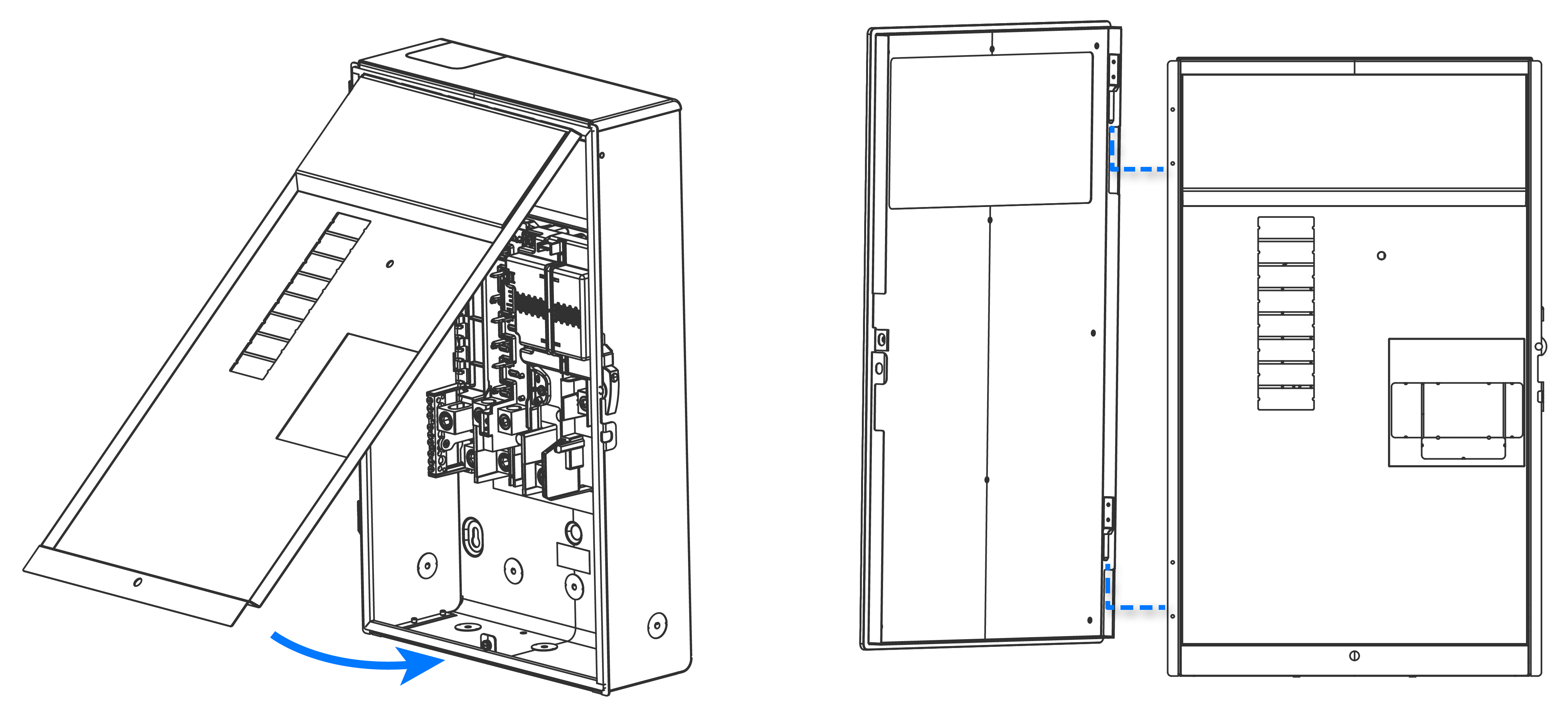 NoteDuring the commissioning process, installers will need to scan a QR code located behind the dead front cover.NoteTo open the door once it has been installed, simultaneously apply inward pressure on the door while pressing in on the top of the latch (located on the right-hand side of the enclosure) as shown below.
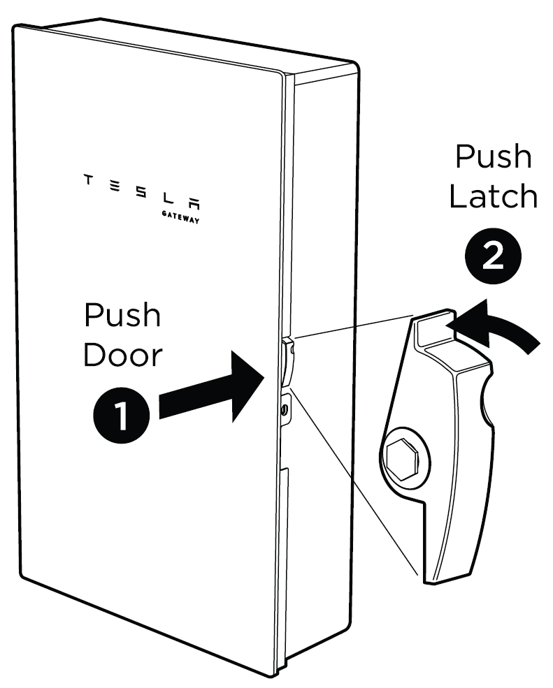
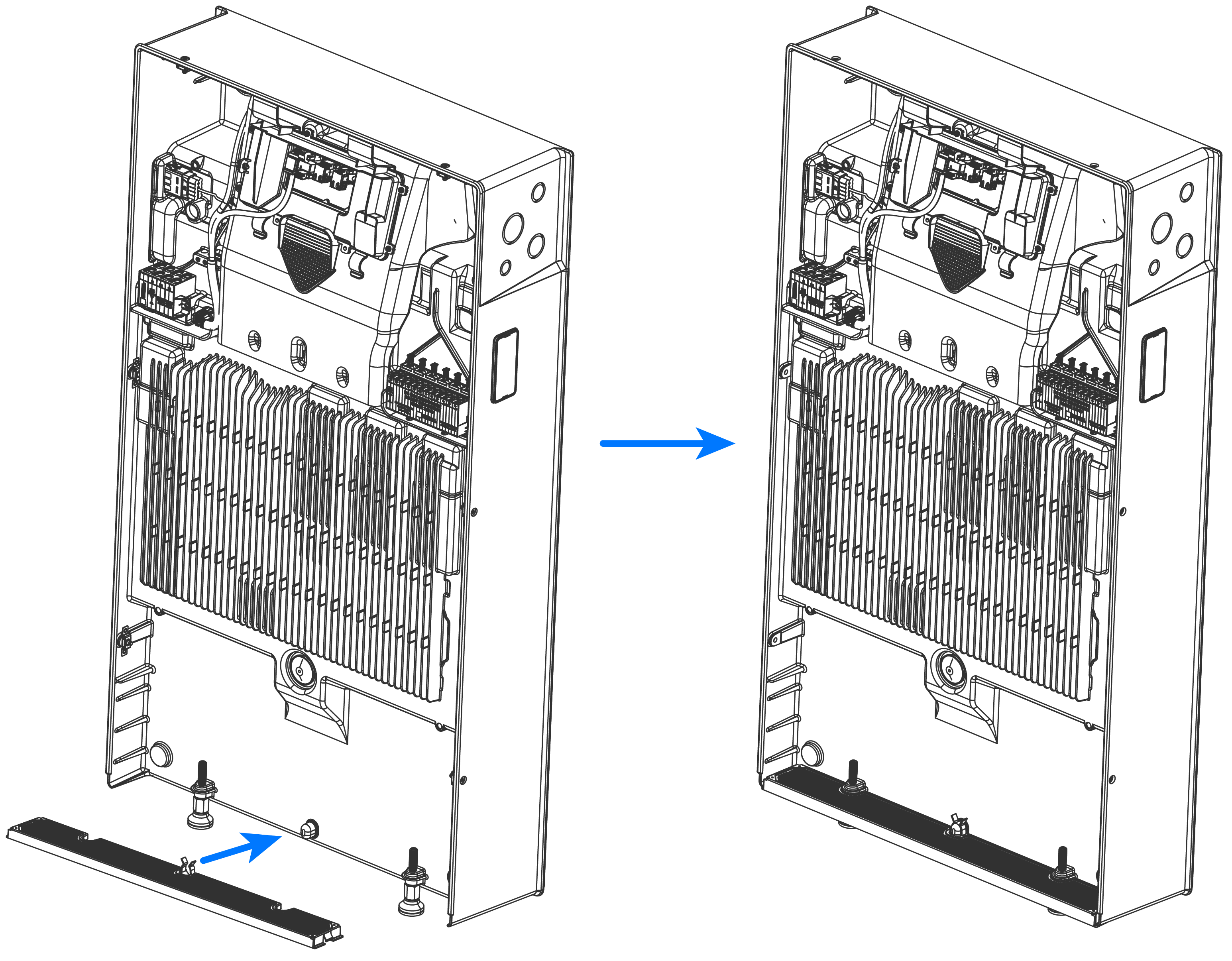
- Arrange all wires neatly inside the Powerwall wiring compartment.
-
Install the air intake screen over the opening at the bottom of Powerwall,
ensuring it snaps into place.
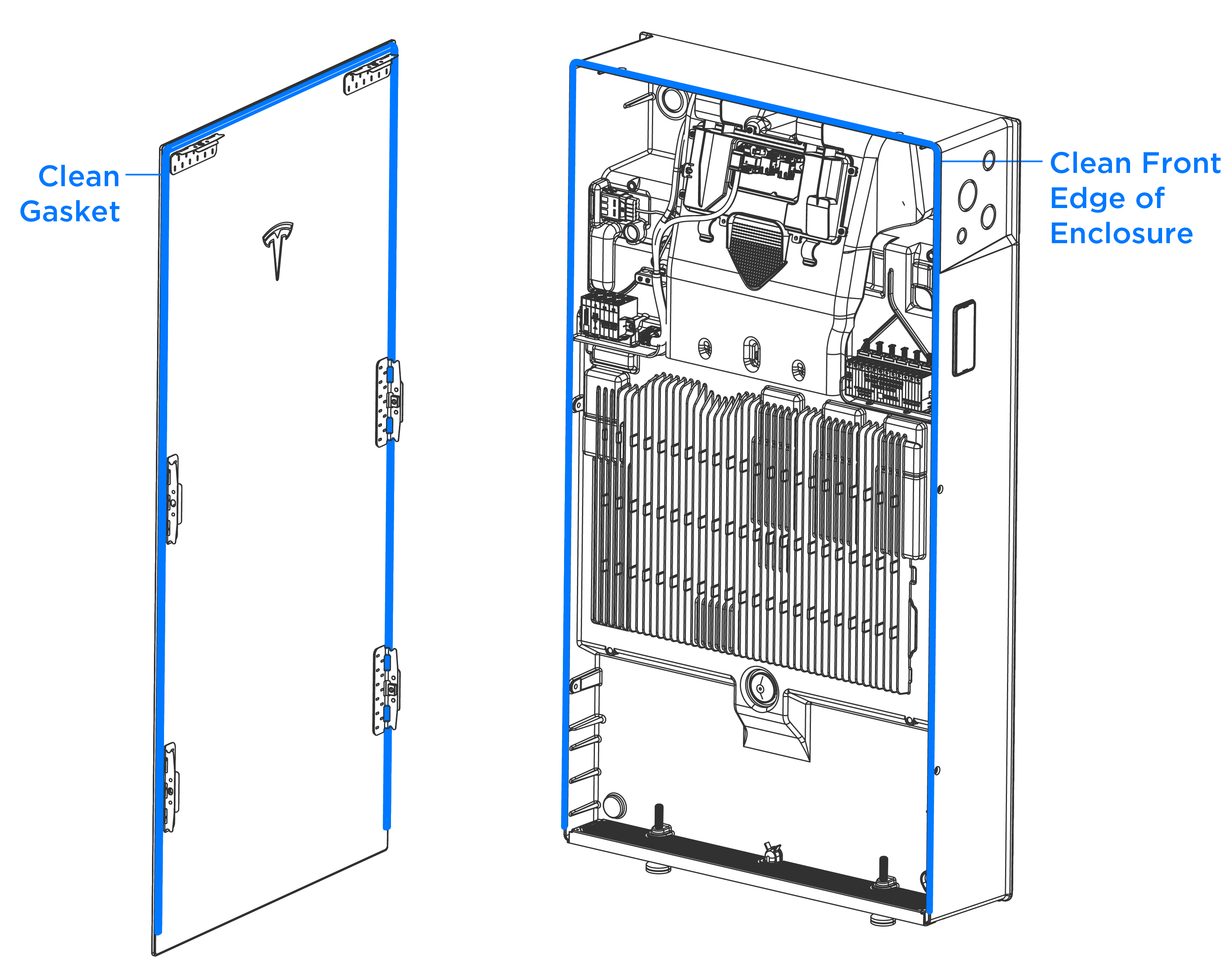
- Clean the front edge of the Powerwall enclosure with a microfiber cloth to remove any debris that might interfere with the seal.
-
Carefully remove the glass front
cover from its packaging and, using a microfiber cloth, clean the sealing gasket
around the edge of the front cover to remove any debris that might interfere
with the seal.
CAUTIONTake extreme care when handling the sealing gasket. Damage to or contamination of the gasket or its mating surface could compromise Powerwall's ingress protection, resulting in product damage.
-
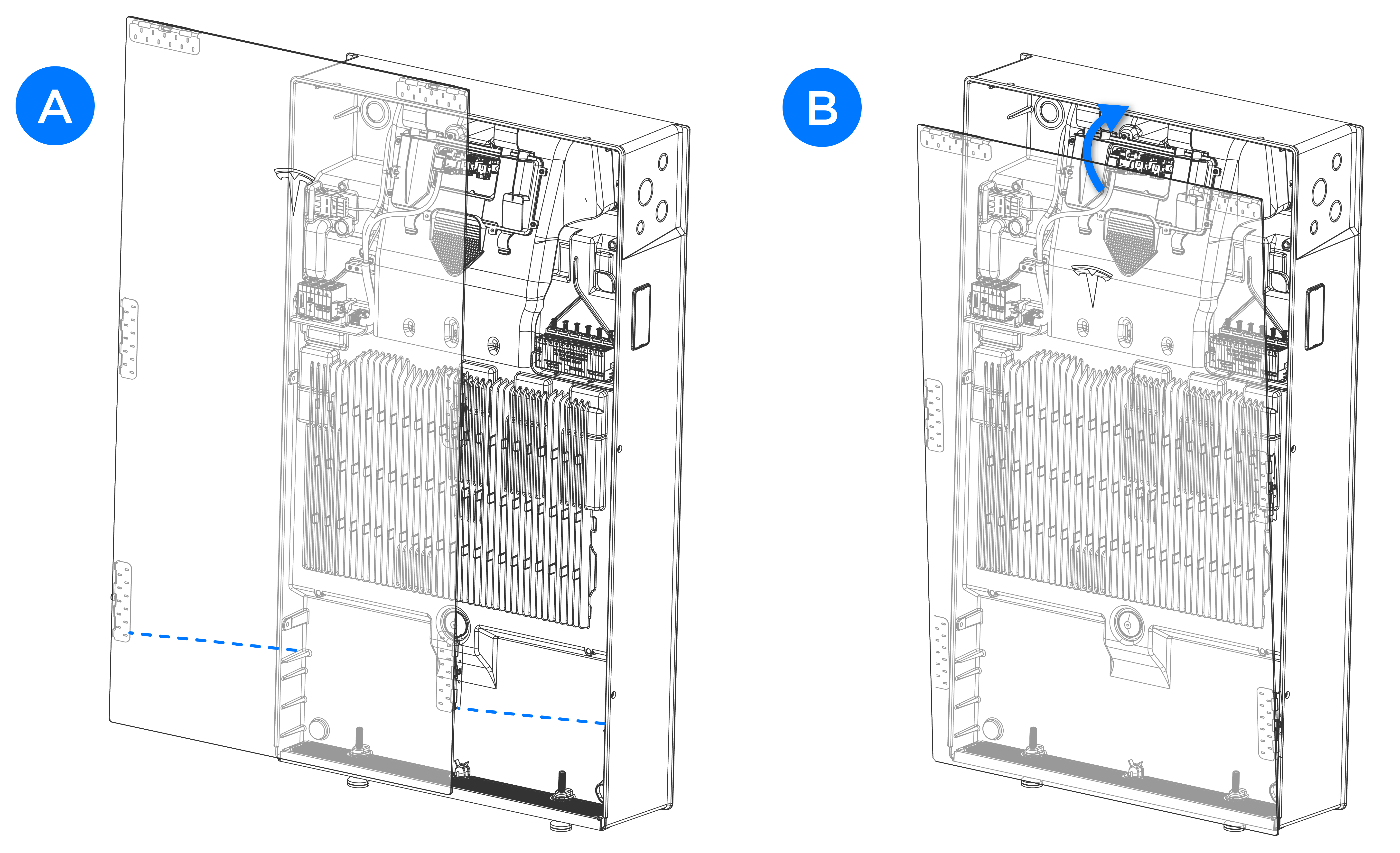
Carefully install the glass front cover:
-
Rotate the front cover
toward the enclosure to engage the top mounting tabs with the enclosure
(B). Maintain
pressure (15-20 lb force) on the front of
the cover to compress the sealing gasket.
CAUTIONMaintain pressure to keep the sealing gasket compressed until all fasteners are installed and tightened. If the sealing gasket is not compressed, the fasteners may thread form in the enclosure, breaking the front cover mounting tabs.
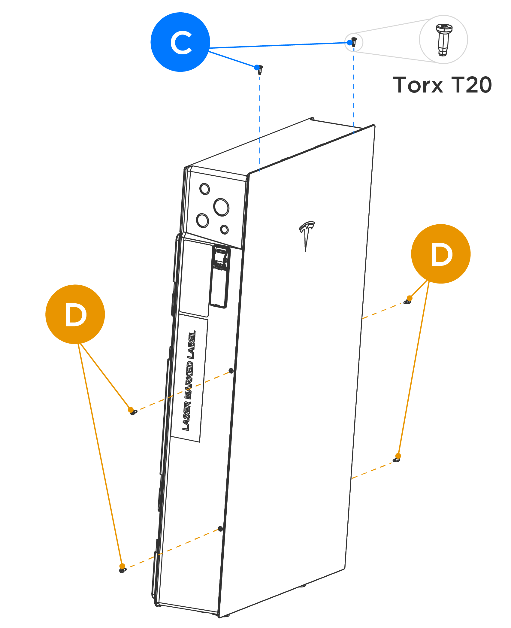
-
Tighten each fastener to
approximately 25 in-lb (2.8 Nm) or hand-tight.
CAUTIONDo not use an impact driver to torque the fasteners.
-
Rotate the front cover
toward the enclosure to engage the top mounting tabs with the enclosure
(B). Maintain
pressure (15-20 lb force) on the front of
the cover to compress the sealing gasket.
- Clearly label all circuit breakers.