Device(s) Not Visible
Symptoms
Device(s) are not scanning in and are not visible on the Devices tab of the System page.
Steps to Troubleshoot
- Confirm the device LED is ON,
indicating the device is powered:
Backup Gateway 2 LED 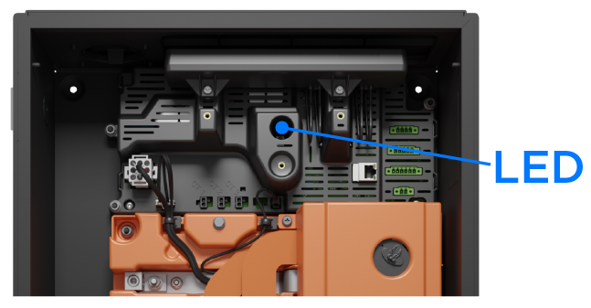
Powerwall+ LED 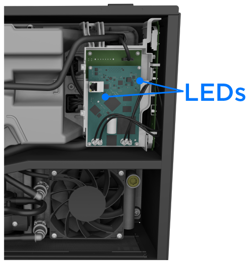
Tesla Solar Inverter 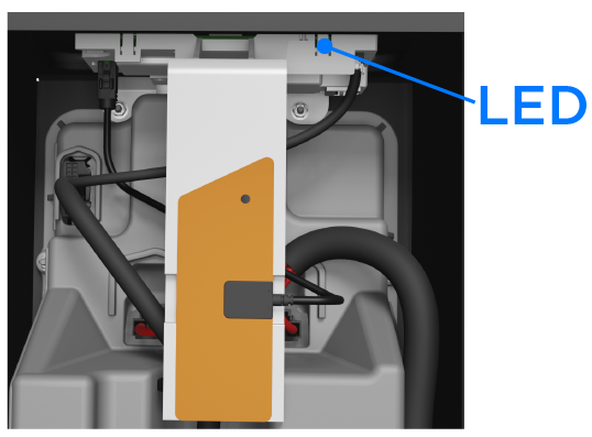
Tesla Solar Inverter with Site Controller 
- If the device is not powered:
- Close (turn ON) the device breaker.
- If the device is a Powerwall, ensure its On/Off switch is turned
ON.NoteIf the Powerwall LED is on and flashing, it is likely there is an issue with the CAN wiring.
- If there are multiple Powerwall units installed, isolate them to determine if
any of the units themselves are the issue. For each unit:
- Connect the Site Controller directly to the Powerwall 2 or Powerwall+ solar assembly via communication wiring as though installing a single unit.
- For Powerwall 2, place a connector with a terminating 120-Ohm resistor in the OUT port of the Powerwall.
- In Tesla One Device Setup, scan for the unit. If it appears, the issue is not with this unit.
- If each of the isolated units appears in Tesla One Device Setup, the issue is with the system wiring.
- Ensure the communication wiring
is correct at each installed unit:
Figure 1. Backup Gateway Communication Wiring 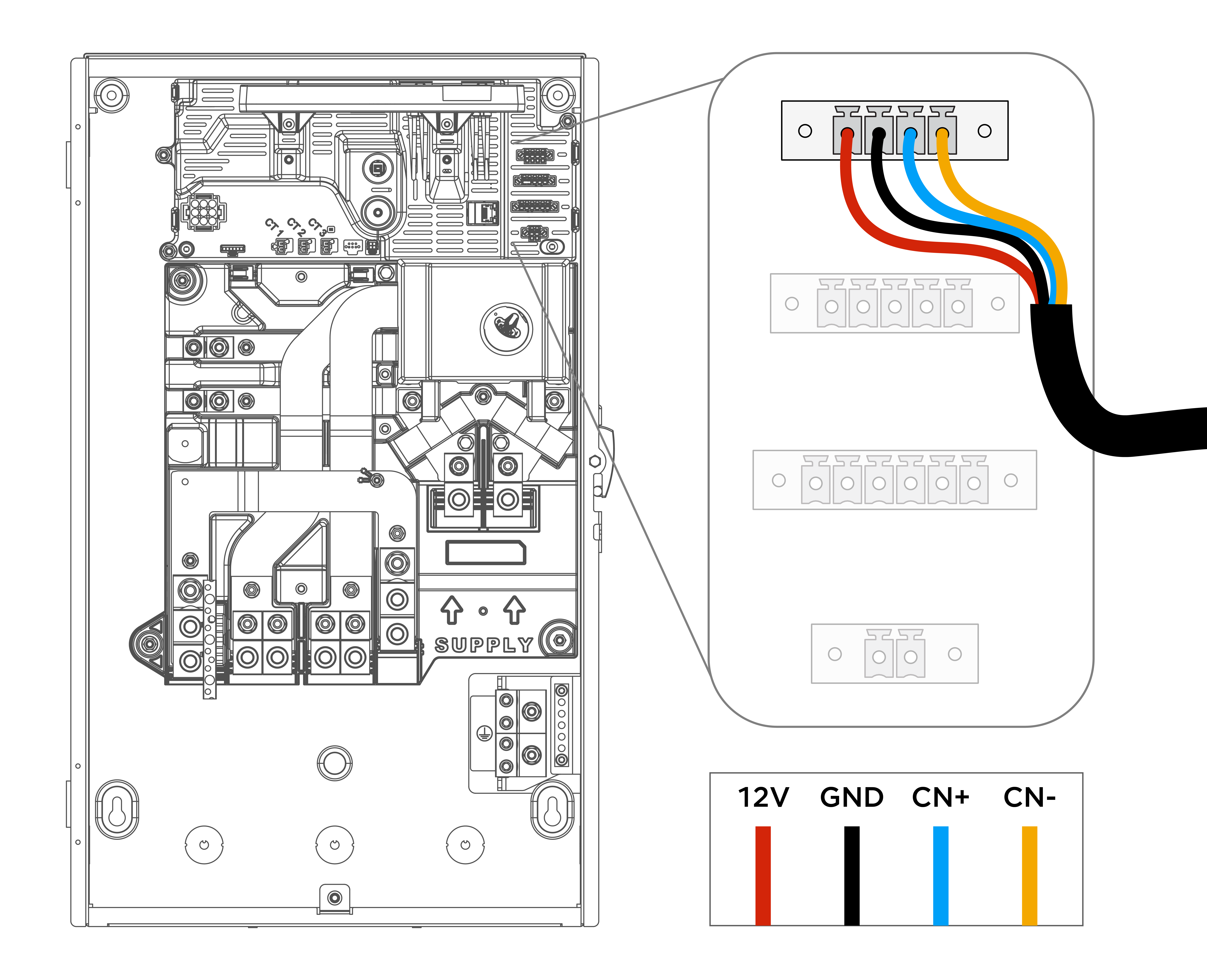
Figure 2. Backup Switch Communication Wiring 
Figure 3. Powerwall Communication Wiring 
Figure 4. Powerwall+ Solar Assembly Communication Wiring 
- Ensure the wiring used meets the minimum requirements as defined in the Powerwall / Powerwall+ installation manual:
- Minimum 600 V rated 4-conductor (twisted pair optional) or double-insulated (with one twisted pair) shielded copper (Cu) cable
- Maximum cable length1 from Backup
Gateway / Backup Switch to Powerwall / Powerwall+:
- 150 ft (45 m) for 16 AWG (1.5 mm2) wire
- 82 ft (25 m) for 18 AWG (0.8 mm2) wire
1Total length of communications cable, including daisy-chained connections, through last unit in chain
- Confirm voltage measurements at
the Powerwall+ solar assembly and
Backup Gateway (if present):
- The Backup Gateway is powered by L1 and L2 on the supply side. Make sure all disconnection/protection devices on the supply side are closed. Confirm voltage measurement of 120V +/-5% for L1-N
- Confirm 12 V output directly at the 12 V+ and GND- pins (pins are called out above). If the output is less than 5 V, there may be a defective power supply
- Confirm 2.4 V output directly at the CN+ and CN- pins (pins are called out above). If the output is less than 2.28 V, there may be a defective power supply. Reach out to Tesla support
- Check for shorts between
any ports and wires (if any voltage measurements show 0V or low voltage
when connected)NoteWiring leads may need to be removed from the connector to accurately measure voltage.
- Check for continuity between the Powerwall+ battery assembly / Powerwall IN and OUT port pins (12V, GND, CN+, and CN-)
- Take photos of voltage measurements, wiring, and probes in case further review is needed
- For additional troubleshooting steps, see the Powerwall Scanning & Verification Best Practices application note on Partner Portal