Power Factor (PF) Not Close to 1
A CT displays Power Factor (PF) not close to 1, Site and Solar power flows are not representative of actual power flows, and/or negative loads are observed on the landing page
When verifying CT placement and location, it is worth checking the Power Factor read by each CT. When metering normal large residential loads such as a space heater, toaster, etc. the loads have predominantly resistive characteristics and a Power Factor close to 1. When testing with loads greater than 1kW and Power Factor is less than 0.8, it is possible there is a problem with the metering configuration. This method of troubleshooting is especially relevant on three phase systems, where a low Power Factor (e.g. ~0.5) may be a sign of a CT being on a different phase than its voltage reference.
Steps to Troubleshoot
- Ensure the meter voltage tap is near the measurement point
- Ensure the voltage taps are spliced into the correct phases of the breaker (see Install a Neurio Remote Energy Meter and CTs in the Residential Energy Metering Guide).
Refer to the following current transformer issues for troubleshooting steps:
- Gateway CTs and Neurio CTs are Overlapping
- Confirm the CTs are facing the
correct way:
- Locate the CT(s) used to measure the source that is displaying incorrect power flow readings.
- Verify the CT(s) are oriented such
that the label is facing toward the source (away from the breaker).
- Solar Current Transformer: Label toward the Inverter
- Site Current Transformer: Label toward the Grid
Figure 1. Tesla 100 A Current Transformer Orientation in Relation to Power Flow 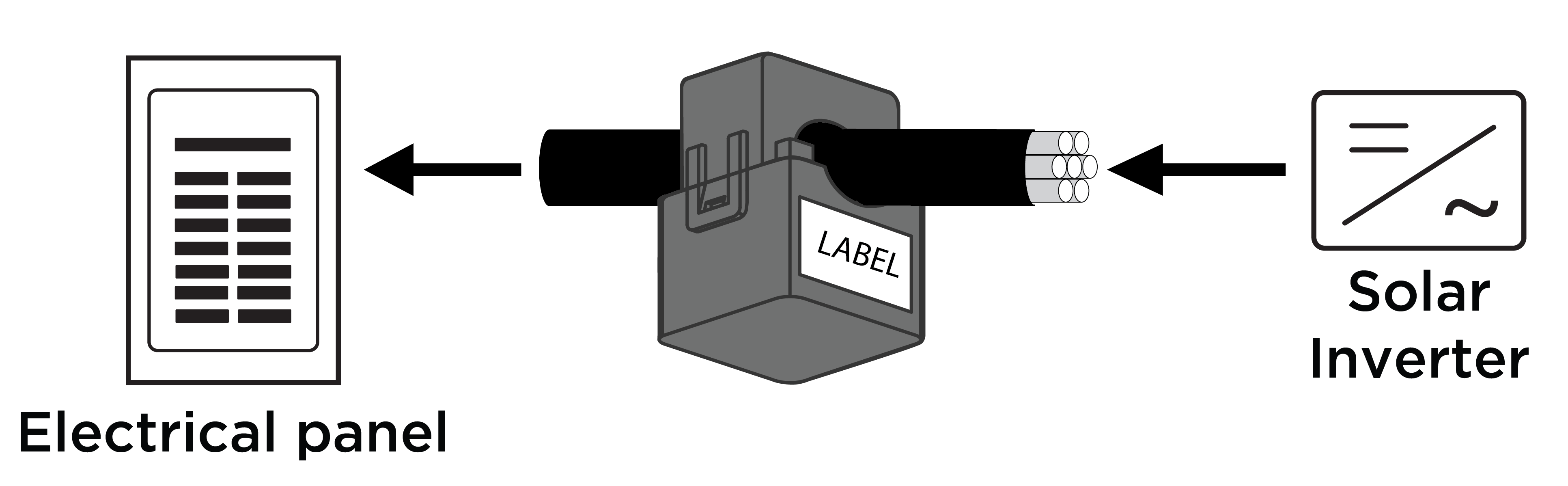
Figure 2. Neurio W2 CT Correctly Oriented to Measure Solar (top) and Incorrectly Oriented (bottom) 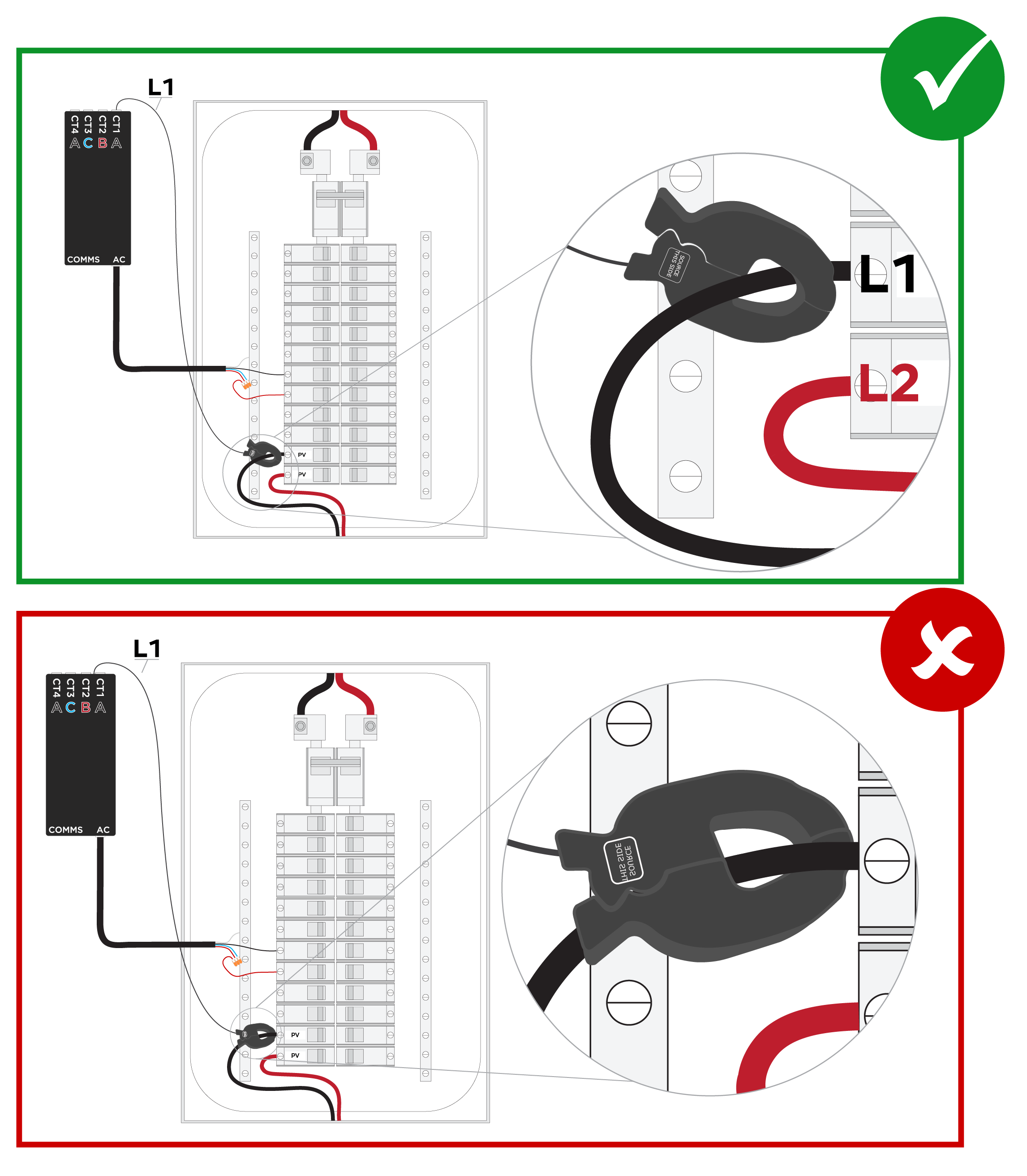
- Confirm the CTs are measuring the
correct phase:
- Locate the CT on the Meter page in Tesla One.
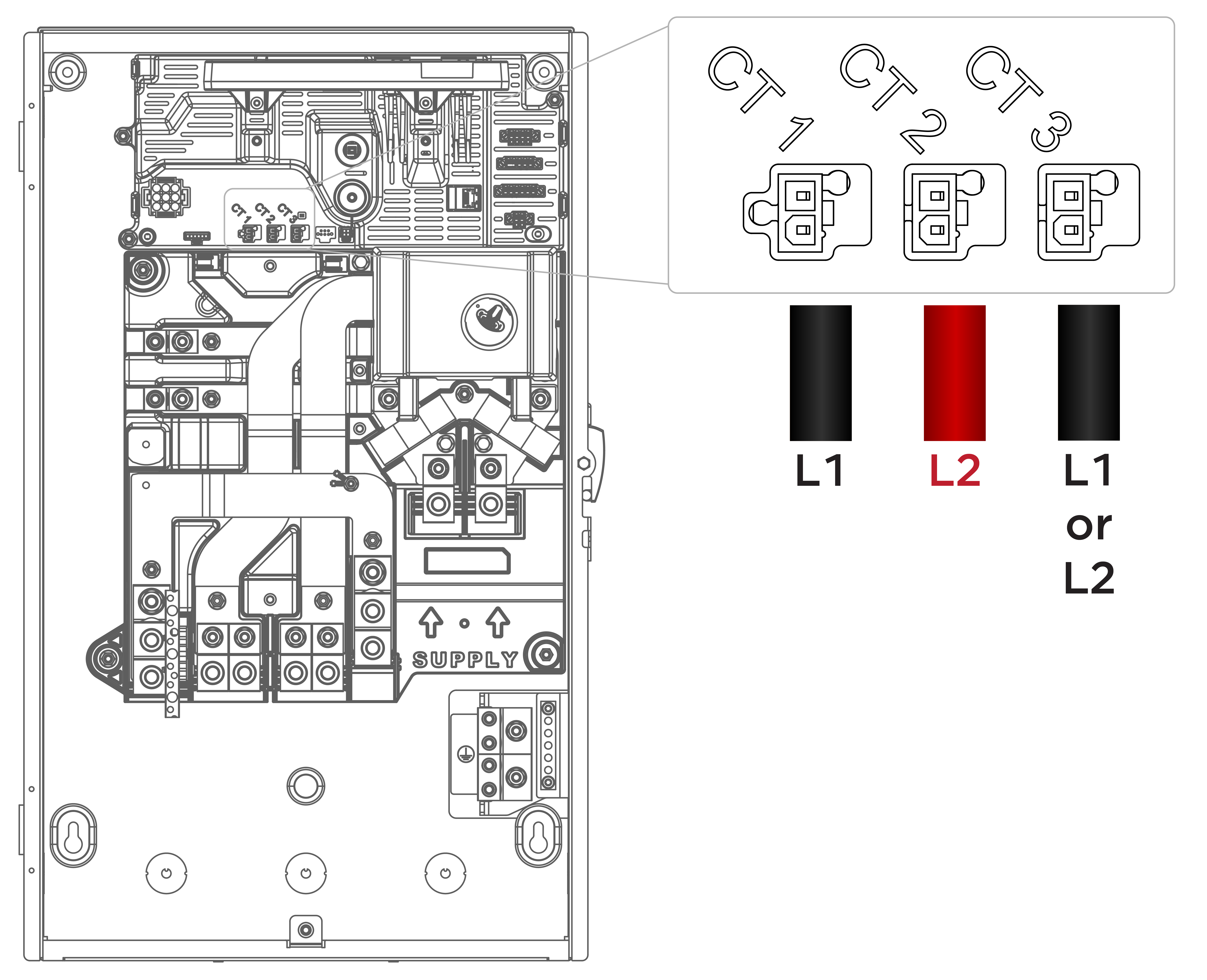
- Determine which phase the CT should
be measuring.NoteIf using Gateway CTs, the ports are CT 1 (Line 1), CT2, (Line 2), CT 3 (defaults to Line 1 but can be configured as Line 2 in Tesla One).
 NoteIf using a Neurio meter, the ports are A (Line 1), B (Line 2), B (Line 2), A (Line 1) and are determined by voltage reference.
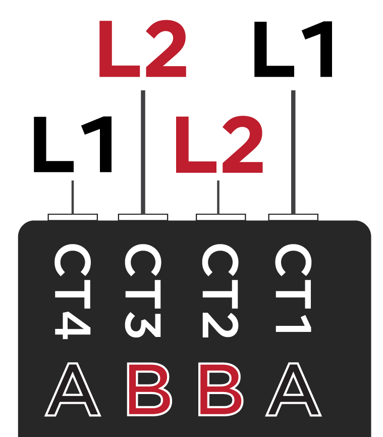
- Verify the CT is measuring the
correct phase.
Figure 3. Gateway CT Measuring Correct Phase (top) and Incorrect Phase (bottom) 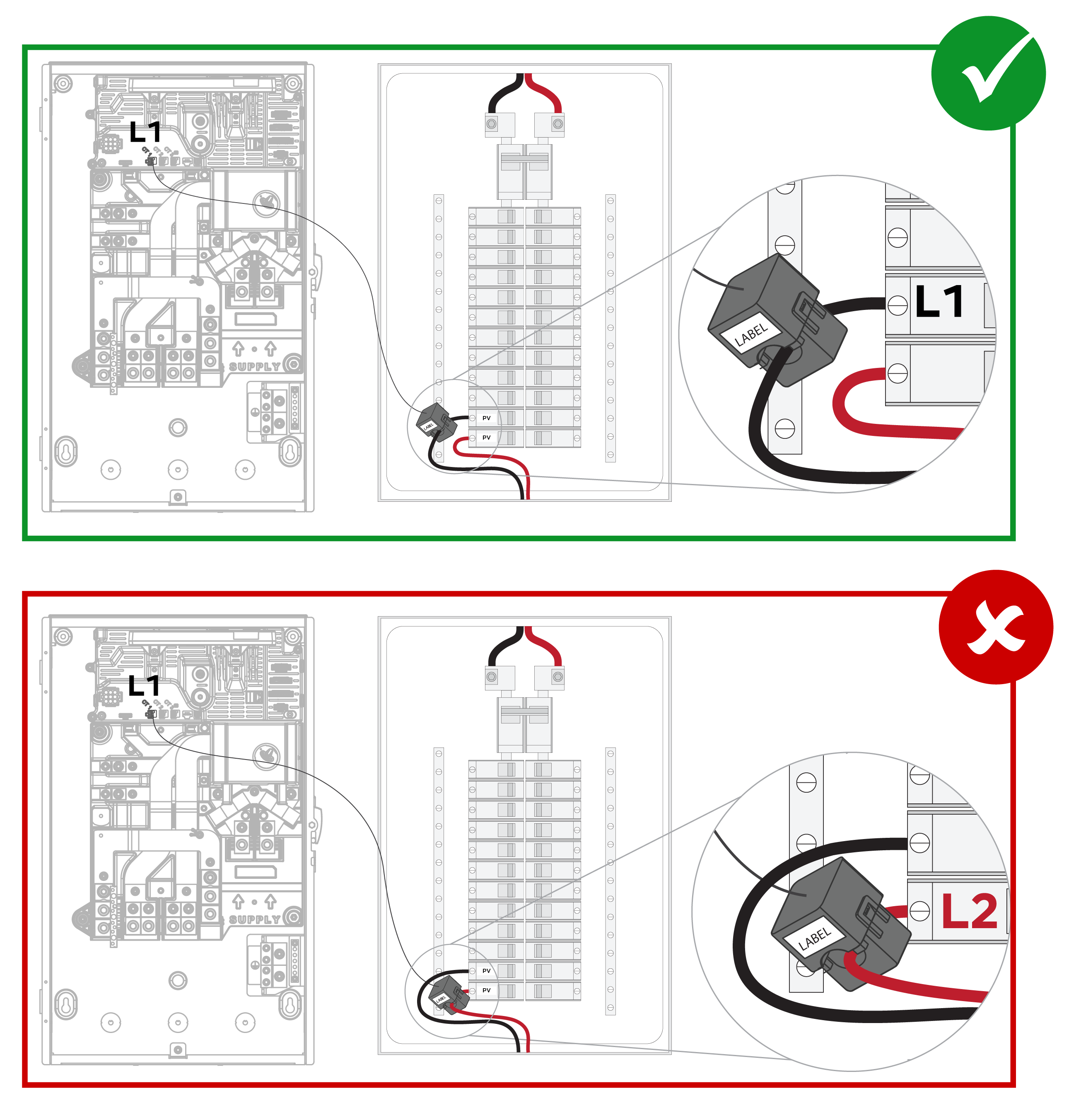 NoteIn the examples above, the CT is monitoring a solar inverter conductor, which is why only (1) CT is required.
Figure 4. Neurio W2 CT Measuring Correct Phase (top) and Incorrect Phase (bottom) 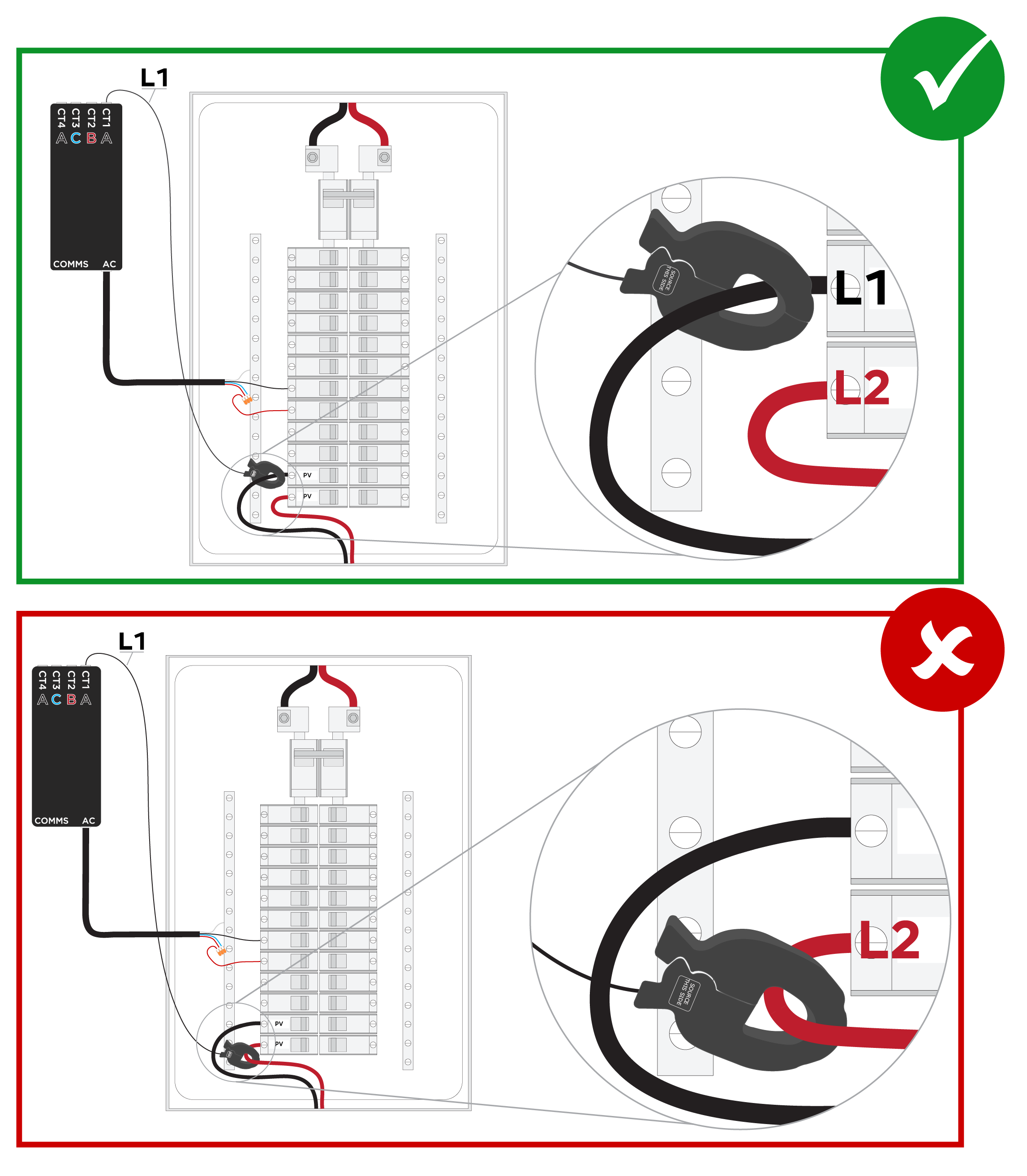 NoteIn the examples above, the CT is monitoring a solar inverter conductor, which is why only (1) CT is required.
- Ensure the CTs have been placed
in the correct location and are measuring the correct conductor(s):
- Verify the CT is clamped properly
around the intended conductor(s). WarningBefore installing, disconnecting, and/or adjusting CTs, ensure the circuits being measured are not energized and the system is completely powered down. Failure to de-energize the system may compromise operator and equipment safety.
- Verify the CT is not capturing any
other conductor(s).NoteIf a site has multiple inverter outputs and their conductors are being grouped, ensure every conductor is captured.
In the first example below, the CT captures the (3) L1 conductors for three solar inverters. In the second example, the CT captures (2) solar inverter conductors and (1) hot tub conductor, leaving the third solar inverter conductor uncaptured.
Figure 5. Solar CT Measuring all PV (top) and Solar CT Measuring Partial PV and a Non-Solar Load (bottom) 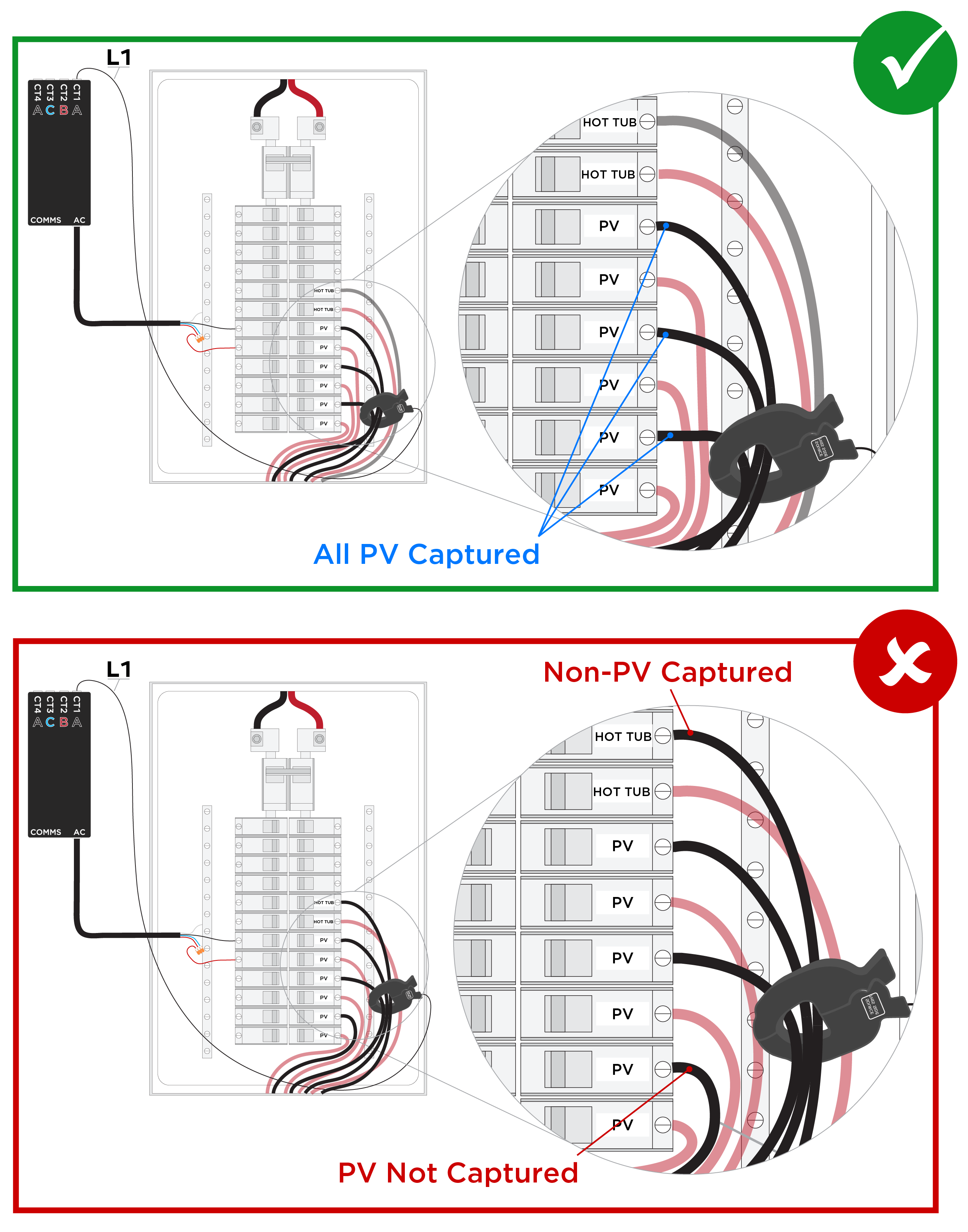
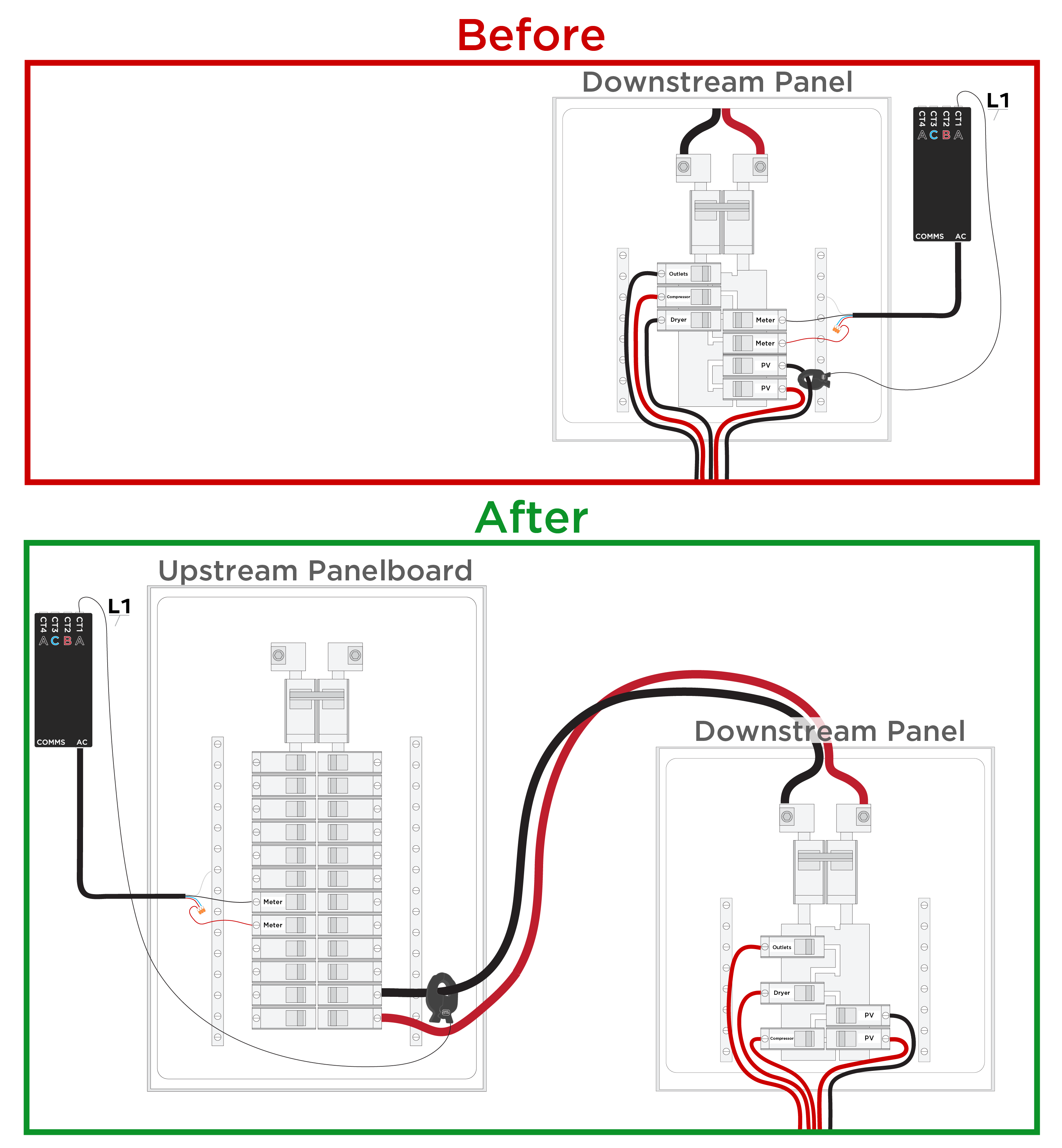
- If solar is in a generation
panel where the only conductors are solar, the entire generation panel can be
measured:
- If there are additional 120V loads in the downstream panel, move them all to the same phase (in the example below, they are moved to L2).
- Move the Neurio meter and CTs to the upstream panel and place the CT on the downstream panel feeder, choosing the opposite phase (in the example below, the CT is placed on L1).
- Configure the CT as Solar (1CTx2).
- Verify the CT is clamped properly
around the intended conductor(s).