Perform Insulation Resistance (Megger) Test to Identify Faulty String
Insulation Resistance Test Overview
Insulation resistance (or Megger) testing is performed by “injecting” potential onto the conductor in the form of DC voltage, with a second conductor or ground conductor as a reference point. Any “leakage" of the potential indicates a fault in the insulation.
- Klein ET600 Tester in 1000V mode
Identify the Faulty String
- Safely shut the system down:
- Initiate Rapid
Shutdown:
- For Powerwall+, push the System Shutdown Switch if one is present, then turn the Enable switch OFF.
- For Tesla Solar Inverter, turn the AC disconnect OFF if one is present, then open the Solar Inverter circuit breaker.
- Open the Powerwall+ / Tesla Solar Inverter circuit breaker (turn OFF) if not already done.
- Remove the DC
Isolator connector.
Figure 2. Tesla Solar Inverter DC Isolator 
- Wait 30 seconds before proceeding with any work.WarningConfirm Powerwall+ / Tesla Solar Inverter is de-energized before proceeding. Confirm the breaker is open (OFF) and solar production is disabled in Tesla One.
- Initiate Rapid
Shutdown:
- Plug the positive and
negative meter tester leads into the meter. If you have a combination megger
and multi-meter, make sure the tester leads are plugged into the ports for
insulation testing.
- Set the tester to
1000V mode.
- Disconnect both (positive and negative) conductors to test a string. The
conductors can be disconnected from the inverter (on the ground) or on the
roof.NoteParalleled strings must be tested independently. This must be done on the roof, and can be done by undoing Y-connectors or removing jumpers inside the combiner box.NoteFor very short strings of two modules, test the short string together with a string that passes the test. Short strings may not be able to be tested by themselves.
- Test the string's positive conductor:
- Connect the positive tester lead (red) to the positive conductor.
- Connect the negative
tester lead (black) to ground / equipment grounding conductor (EGC).
Figure 3. Testing the Insulation Resistance of the Positive Conductor 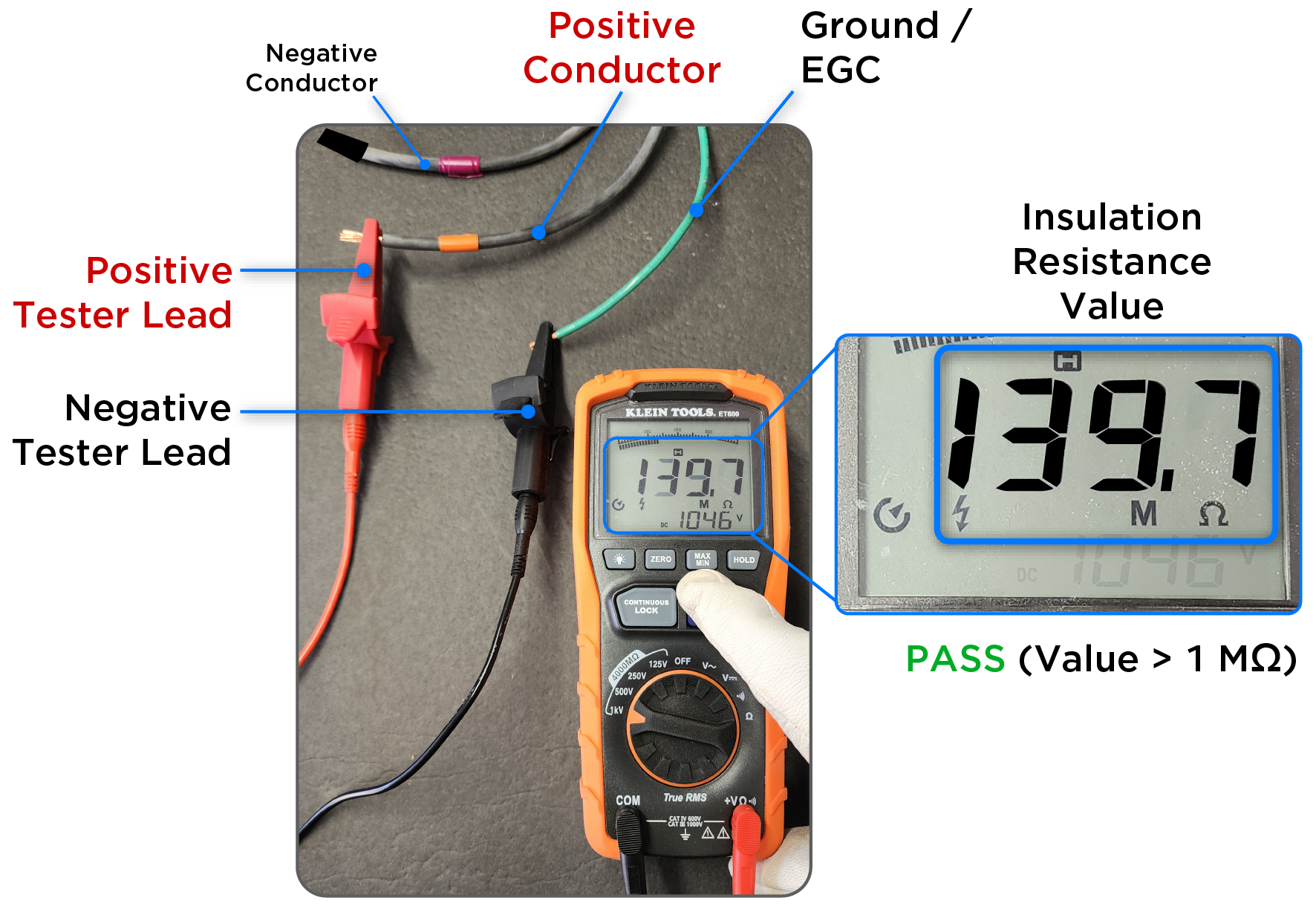
- Tape the ends of the wire on the opposite end of the run to help isolate.
- Push the TEST button on the tester until the reading stabilizes.
- If the insulation resistance is less than 1 Mega-Ohm, this string is
causing the isolation failure. NoteString voltage to ground (V DC) is expected to be a high value because it indicates an open circuit.
- Test the string's negative conductor:
- Connect the positive tester lead (red) to the negative conductor.
- Connect the negative
tester lead (black) to ground / EGC.
Figure 4. Testing the Insulation Resistance of the Negative Conductor 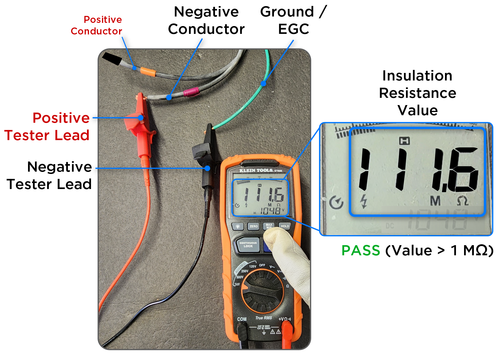
- Tape the ends of the wire on the opposite end of the run to help isolate.
- Push the TEST button on the tester until the reading stabilizes.
- If the insulation resistance is less than 1 Mega-Ohm, this string is
causing the isolation failure. NoteString voltage to ground (V DC) is expected to be a high value because it indicates an open circuit.
Identify the Failure in the Faulty String
To find the failure, perform a close inspection of all the components in the faulty string:
- At the Powerwall+ / Tesla Solar Inverter, look for poor wire termination (wires not fully seated in terminals, wire strands are frayed)
- Inspect where the wires exit conduit, as nicked wires may occur here
- Check for wires pinched by mounting hardware
- For Solar Roof installations, check for wires damaged by screws (screws may be accidentally run through wires when installing the tiles)
- Check for improper field-made connectors or improper crimps
- Look for evidence of damaged
modules:
- Microcracks
- Signs of water intrusion
- Module leads are bent at sharp angles
- For the faulty string, try testing the string with the DC grounding conductor (EGC) removed from the inverter's ground terminal; if the string passes self-test with the grounding conductor removed, it is likely the string is faulting to ground somewhere
If any of the above issues are observed, repair or replace the equipment. For instance if the issue is caused by a nicked wire in the conduit body, cut out the damaged wire and splice the remaining segments together or replace the wire if splicing is not possible. If the issue is caused by a nicked wire in the middle of the array, cut the wire and crimp PV connector heads on either remaining segment, or replace the entire section of wire (whichever is easiest).
If none of the issues above are observed, see MCI Diode Test and Resistance Test (MCI Health Tests) to determine if a faulty MCI is causing the isolation failure.