Door Ring Inner
 Correction code:
10100132102,
10100144502
NOTE:
Unless explicitly stated in the procedure, the above
correction code includes all Collision Repair and Service
repair work required to perform this procedure, including
the linked Collision Repair procedures and linked Service
procedures. Do not stack Collision Repair correction
codes unless explicitly told to do so. Depending
on the damage to the vehicle, additional repairs may be
required.
Correction code:
10100132102,
10100144502
NOTE:
Unless explicitly stated in the procedure, the above
correction code includes all Collision Repair and Service
repair work required to perform this procedure, including
the linked Collision Repair procedures and linked Service
procedures. Do not stack Collision Repair correction
codes unless explicitly told to do so. Depending
on the damage to the vehicle, additional repairs may be
required.
Repair Information
- Any individual section or any combination of sections of the Door Ring Inner can be replaced so long as the referenced cut lines from the Door Ring Inner Section Descriptions portion of this document are used.
- Review all collision repair general practices and safety documentation and wear the appropriate PPE (Personal Protective Equipment) before beginning this procedure.
- Properly mount the vehicle on a frame bench when performing this procedure.
Parts List
| Quantity | Description | Image / Notes |
|---|---|---|
| 1 | MY ASY-DR RING INR (Door Ring Inner) |
|
| 9 | Structural Bulb Rivet, 6.5 mm | |
| 4 | High Strength Structural Rivet, 6.5 mm | |
| 6 | Flow Form Rivet S18 | |
| 6 | Bolt BOLT & WSHR[FL],M8-1.25x32 | Tesla part number 1119448-00-A. |
| 1 | Bolt T2000,M8x1.25-30 | Tesla part number 1637725-00-A. |
| 7 | Bolt, Torx-head BOLT,TEP,M10-1.5x35 | Tesla part number 1618776-00-B. |
When ordering parts, refer to the Parts Catalog and enter the VIN of the vehicle being repaired to find the correct parts (and the part numbers) for the vehicle. Alternatively, use the search function in the Parts Catalog to find a specific part for the vehicle.
Door Ring Inner Section Descriptions
| Door Ring Inner, Subassemblies, and Subassembly Sectioning | |
|---|---|
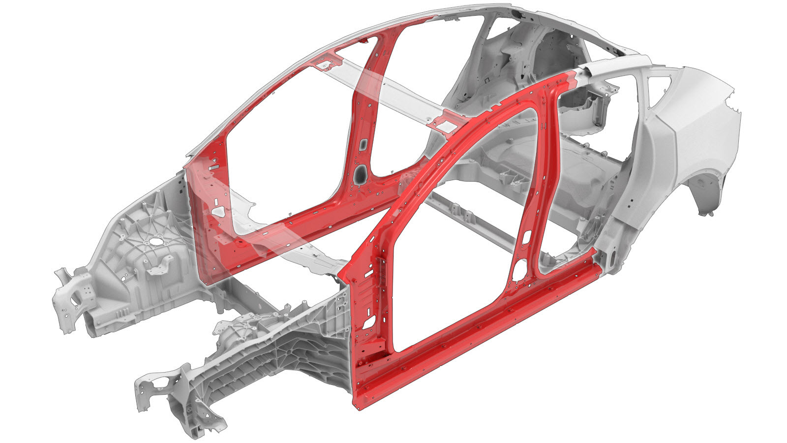
| The Door Ring Inner (shown below) is a single component, and can be replaced as a single repair: | Alternatively, instead of replacing the complete Door Ring Inner, areas of the Door Ring Inner can be replaced using portions of the Door Ring Inner service part using the cut lines described in this document. |
|
|
|
| Door Ring Inner (Complete) | Door Ring Inner Sections |
| Door Ring Inner Section Descriptions | |
|---|---|
|
A–Pillar Section Cut Line Reference Line/Point
Note
Create a reinforcement plate
80 mm wide, and install it as
indicated. |
Hinge Pillar to A-Pillar Cut Line A-Pillar to B-Pillar Cut Line Hinge Pillar to A-Pillar Reinforcement Plate A-Pillar to B-Pillar Reinforcement Plate |
|
Hinge Pillar Section Cut Line Reference Line/Point
Note
Create and install reinforcement plates
and install them as
indicated. Note Each reinforcement plate
should be 80 mm wide. |
Hinge Pillar to A-Pillar Cut Line Hinge Pillar to Sill Cut Line Hinge Pillar to A-Pillar Reinforcement Plate Hinge Pillar to Sill Reinforcement Plates
|
|
B–Pillar Section Cut Line Reference Line/Point
Note
Create a reinforcement plate
80 mm wide, and install it as
indicated. |
A-Pillar to B-Pillar Cut Line B–Pillar to Sill Cut Line A-Pillar to B-Pillar Reinforcement Plate Sill to B-Pillar Reinforcement Plates
|
|
Sill Section Cut Line Reference Line/Point
Note
Create and install reinforcement plates
and install them as
indicated. Note Each reinforcement plate
should be 80 mm wide. |
Hinge Pillar to Sill Cut Line Sill to B-Pillar Cut Line Hinge Pillar to Sill Reinforcement Plates
Sill to B-Pillar Reinforcement Plates
|
Repair Procedure
-
Remove the necessary portion of the
Door Ring Outer.
-
For the Hinge Pillar, Sill or the
B-Pillar section repair only: Remove the Side Sill Insert.
- If replacing a section of the Door Ring Inner: Mark the Door Ring Inner at the section cut line locations described in the Door Ring Inner Section Descriptions.
-
Remove the original component.
- or Factory Spot Welds
-
Remove the original component.
- or Factory Spot Welds
- or Bolt, Torx-head
NoteRetain the bolts for re-installation in a later step. -
Remove the original component.
NoteRetain the bolts for re-installation in a later step.
-
Remove the original component.
- or Factory Spot Welds
- Bolt
NoteThe bolt circled in red may not be present in all vehicles. - Remove the original component.
- For section repairs only: Create backing plates or reinforcement plates as described in the Door Ring Inner Section Descriptions.
-
Prepare for installation.
NoteA red X indicates a location where a factory-installed fastener is not being replaced. Secure this location using structural adhesive only.
- or Structural Bulb Rivets, 6.5 mm
- or Installation Spot Welds
- Prepare for installation.
-
Prepare for installation.
- or High Strength Structural Rivets, 6.5 mm
- or Structural Bulb Rivets, 6.5 mm
- or Bolt, Torx-head
- or Installation Spot Welds
- Prepare for installation.
-
Prepare for installation.
NoteReplace the bolt circled in red only if it was present on the original component.
- or Installation Spot Welds
- Prepare for installation.
- Apply structural adhesive to the mating surfaces on the vehicle and the new component or components.
- For section repairs only: Install reinforcement plates as described in the Door Ring Inner Section Descriptions.
-
Install the new component or components.
Torque bolts as follows:
- Bolt Tesla part number 1637725-00-A: 48 Nm.
- Bolt Tesla part number 1119448-00-A: 35 Nm.
- Bolt, Torx-head Tesla part number 1618776-00-B: 65 Nm.
-
Perform resistance spot
welding.
- or Installation Spot Welds
WarningFailure to follow all welding safety precautions, including the use of personal protective equipment, could result in serious injury or property damage. Only technicians who have completed Tesla’s approved welding training are authorized to weld structural components on Tesla vehicles.CAUTIONDo not weld on a Tesla vehicle before performing the Vehicle Electrical Isolation Procedure (refer to the vehicle-specific Service Manual for more information on the Vehicle Electrical Isolation Procedure). Welding on a Tesla vehicle with an energized high or low voltage system might damage vehicle components. -
For the Hinge Pillar, Sill or the
B-Pillar section repair only: Install the Side Sill Insert.
-
Install the necessary portion of the
Door Ring Outer.
- Perform any necessary post-repair operations.