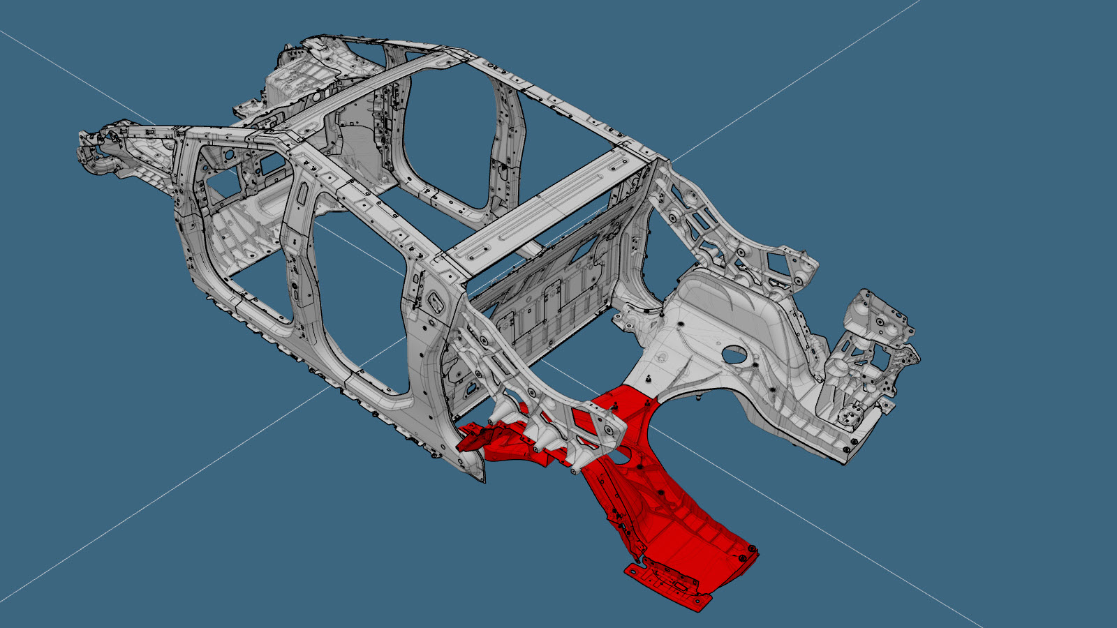
Rear Under Body (Section)
 Correction code:
10102001002
10102001102
NOTE:
Unless explicitly stated in the procedure, the above
correction code includes all Collision Repair and Service
repair work required to perform this procedure, including
the linked Collision Repair procedures and linked Service
procedures. Do not stack Collision Repair correction
codes unless explicitly told to do so. Depending
on the damage to the vehicle, additional repairs may be
required.
Correction code:
10102001002
10102001102
NOTE:
Unless explicitly stated in the procedure, the above
correction code includes all Collision Repair and Service
repair work required to perform this procedure, including
the linked Collision Repair procedures and linked Service
procedures. Do not stack Collision Repair correction
codes unless explicitly told to do so. Depending
on the damage to the vehicle, additional repairs may be
required.
Repair Information
- Review all collision repair general practices and safety documentation and wear the appropriate PPE (Personal Protective Equipment) before beginning this procedure.
- Properly mount the vehicle on a frame bench when performing this procedure.
- The Rear Under Body is a single component, and can be replaced as a single repair, as described in the Rear Under Body (Complete) procedure. Alternatively, instead of replacing the complete Mast Assembly, the LH or RH side of the Rear Under Body can be replaced using a Rear Under Body Half Section service part and the top and bottom reinforcement plates described in the Parts List, and the instructions in the Repair Procedure.
Parts List
| Quantity | Description | Image / Notes |
|---|---|---|
| 1 | ASSEMBLY - REAR UNDER BODY HALF SECTION (Rear Under Body Half Section) | |
| 1 | TOP STAMPING | |
| 1 | BOTTOM STAMPING | |
| 2 | PLUG |
Tesla part number 1870761-00. |
| 13 | High Strength Structural Rivet, 6.5 mm | |
| 4 | Structural Flange Rivet | |
| 3 | Bolt BLT,HHL,M10x33 | Tesla part number 1851387-00. |
When ordering parts, refer to the Parts Catalog and enter the VIN of the vehicle being repaired to find the correct parts (and the part numbers) for the vehicle. Alternatively, use the search function in the Parts Catalog to find a specific part for the vehicle.
Repair Procedure
- Remove the Tailgate Latch and Striker - LH Body - Side Hinge, Tailgate (Remove and Install).
- Remove the Striker - Tailgate (Remove and Install).
- Remove the Tow Hitch (Remove and Install).
- Remove the Bed Side Outer Assembly - LH (Long Range) (Remove and Install).
- LH Component Only: Remove the Busbar - Charge Port (Remove and Install).
- Remove the Tonneau Lower Assembly (Remove and Install).
- Remove the Reservoir - Air Suspension (Remove and Install).
- Remove the Compressor - Air Suspension (Remove and Install).
- Remove the Airline Bundle - LH (Remove and Install).
- Remove the Airline Bundle - RH (Remove and Install).
- Remove the Airline Bundle - Rear (Remove and Install).
- Remove the HV Battery Assembly (Long Range) (Remove and Install).
- Remove the Subframe - Rear (Dual Motor) (Remove and Install).
- Remove the Brake Hose - Rear - LH (Remove and Replace).
- Remove the Module - Air Spring - Rear - LH (Remove and Install).
- Remove the Control Arm - Upper - Rear - LH (Remove and Install).
-
On the original component,
verify the location of the center point for the rear-most access hole.
The center point for the rear-most access hole should be located 155 mm to the rear of the indicated hole (measurement A).NoteIf the center point marked on the component is 150 mm, move the center point 5 mm to the rear of the marked center point (measurement B).Reference Line/Point
- A = 155 mm
- B = 5 mm
-
On the original component,
cut the rear access holes.
Cut LineNoteUse a 1 1/8 inch (29 mm) carbide-tipped hole saw to create the holes.
-
Separate the Rear Under Body
Sections.
Cut next to the raised cut line on the damaged side of the component.Cut LineNoteIf the Rear Under Body is damaged on both sides of the raised cut line, sectioninng is not allowed and the entire component must be replaced as described in the Rear Under Body (Complete) procedure.
-
Remove the original component.
-
Bulk cut and remove the Rear Under
Body casting.
Cut the Rear Under Body near the C-Pillar Inner area as shown, then remove the cut portion of the original component. (Removing casting material will assist with the heating and separating process.)NoteTo prevent damage to the C-Pillar Inner, when cutting near the inboard side of the C-Pillar Inner, cut only in the area shown in yellow (do not cut in the area shown in red).
Cut Line
-
Remove the remaining portion of the original component.
Use heat and separation methods, then grind as necessary to remove the remaining casting material (shown in red) near the C-Pillar Inner area.NoteUse caution to make sure that the C-Pillar Inner is not damaged when removing the remaining portion of the original Rear Under Body casting.
-
If the tab highlighted in red is present, remove the tab and grind the panel
until smooth before proceeding.
-
Prepare for installation.
Trim the remaining portion of the existing component on the vehicle to fit.NoteThe maximum gap between new and existing components is 3 mm.NoteA red X indicates a location where a factory-installed fastener is not being replaced. Secure this location using structural adhesive only.
or High Strength Structural Rivets, 6.5 mm
or Structural Flange Rivets, 6.5 mm
or Bolts
- Apply structural adhesive to the mating surfaces on the vehicle and the new component or components.
-
Install the new component or components.
Torque the bolts to 90 Nm.NoteFill any gaps with structural adhesive.
-
Trim the Rear Rocker Step
Reinforcement to allow clearance for the plug that covers the rear access
hole.
Cut Line
Reference Line/Point
- C = 7 mm.
- D = 32 mm.
-
Install the plugs to cover the access
holes.
NoteApply seam sealer to the bottom side of each plug before installation, and remove any visible seam sealer around the outside edge of the plug after installation.NoteRemove any visible seam sealer from around the access hole plugs that would be under the foam gasket of the Rear Rocker Step Reinforcement.
-
Install the Tailgate Tower.
-
Install the Rear Fascia Bracket.
-
Install the Sail Datum Bracket.
- Perform any necessary post-repair operations.
- Install the Control Arm - Upper - Rear - LH (Remove and Install).
- Install the Module - Air Spring - Rear - LH (Remove and Install).
- Install the Brake Hose - Rear - LH (Remove and Replace).
- Install the Subframe - Rear (Dual Motor) (Remove and Install).
- Install the HV Battery Assembly (Long Range) (Remove and Install).
- Install the Airline Bundle - Rear (Remove and Install).
- Install the Airline Bundle - RH (Remove and Install).
- Install the Airline Bundle - LH (Remove and Install).
- Install the Compressor - Air Suspension (Remove and Install).
- Install the Reservoir - Air Suspension (Remove and Install).
- Install the Tonneau Lower Assembly (Remove and Install).
- LH Component Only: Install the Busbar - Charge Port (Remove and Install).
- Install the Bed Side Outer Assembly - LH (Long Range) (Remove and Install).
- Install the Tow Hitch (Remove and Install).
- Install the Striker - Tailgate (Remove and Install).
- Install the Tailgate Latch and Striker - LH Body - Side Hinge, Tailgate (Remove and Install).