05/09/2023 17:46:27
Step 5: Wire the Powerwall Units
-
Connect the communication ports
of the two Powerwalls by doing the following:
- Run the provided 5-conductor communication harness between the Powerwall wiring compartments. At the first Powerwall, cut back the drain wire; the drain wire should be terminated only at the second Powerwall.
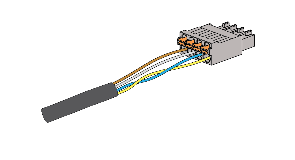
NoteThe orange conductor is unused in Powerwall 2 AC installations.- Attach the provided
Phoenix connector to one end of the harness, and attach the extra
Phoenix connector that came with the Powerwall to the other end of the
harness. See Appendix B: Wiring Reference for additional wiring information.
- Connect the communication OUT connector of the first Powerwall to the communication IN connector of the second Powerwall.
- To ground the
drain wire:
- Strip the end of the equipment grounding conductor lead and wrap the communication drain wire around the grounding conductor lead.
- Insert
the drain wire and grounding conductor lead into the
second Powerwall chassis ground lug. The ground lug is
identified with the following symbol:

- Tighten the screw in the ground lug to 4.5 Nm (40 lb-in).
NoteThere will be a drain wire grounded in each Powerwall in the chain. For each pair of components (Gateway and first Powerwall, first Powerwall and second Powerwall, etc.), the drain wire is cut at the first component and grounded at the second.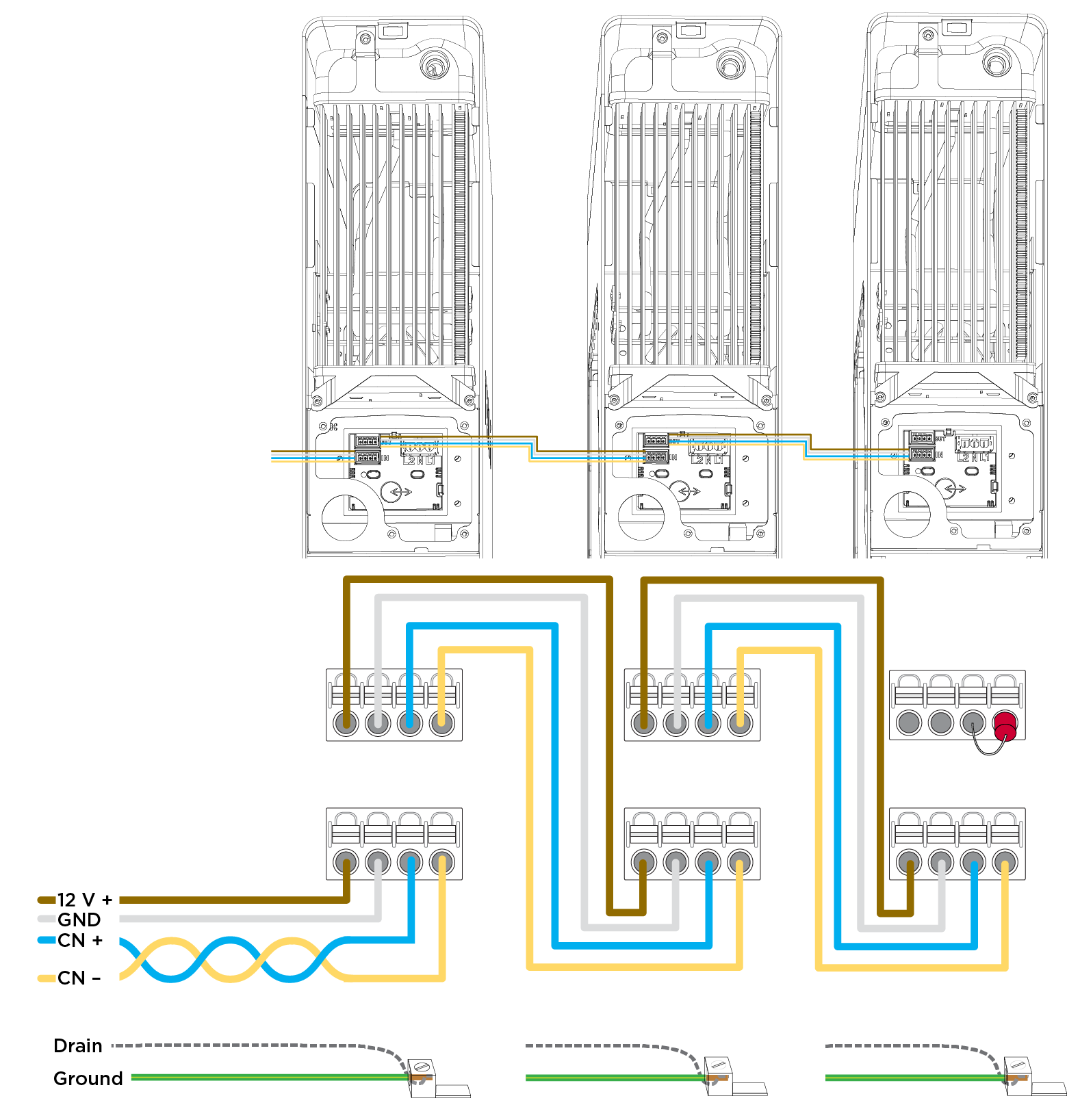
Figure 1. Connecting Powerwall Communication Ports 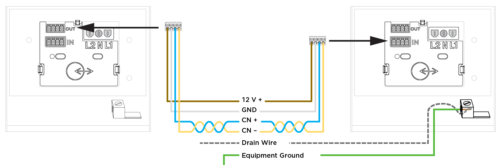
- In the last Powerwall in the communication chain, plug the 4-pin Phoenix connector with the terminating 120-Ohm resistor into the top 4-pin socket (labeled “OUT”).
- Connect each AC Powerwall to the main or sub electrical panel of the installation (depending on the system configuration) according to the electrical service type.
- On the Powerwall side, strip the ends of the wires and attach them to the corresponding leads on the 3-pin AC power harness.
-
Plug the AC power harness into
the AC connector in the Powerwall wiring compartment. Ensure that the connector
clicks into place.
NoteEach Powerwall connection to the main electrical panel requires an independent 30 A circuit breaker. This breaker serves as the disconnect for the Powerwall, and must be wired in accordance with local wiring codes and regulations.
- Reconnect the power and communications leads that were disconnected from the first Powerwall at the beginning of the installation.