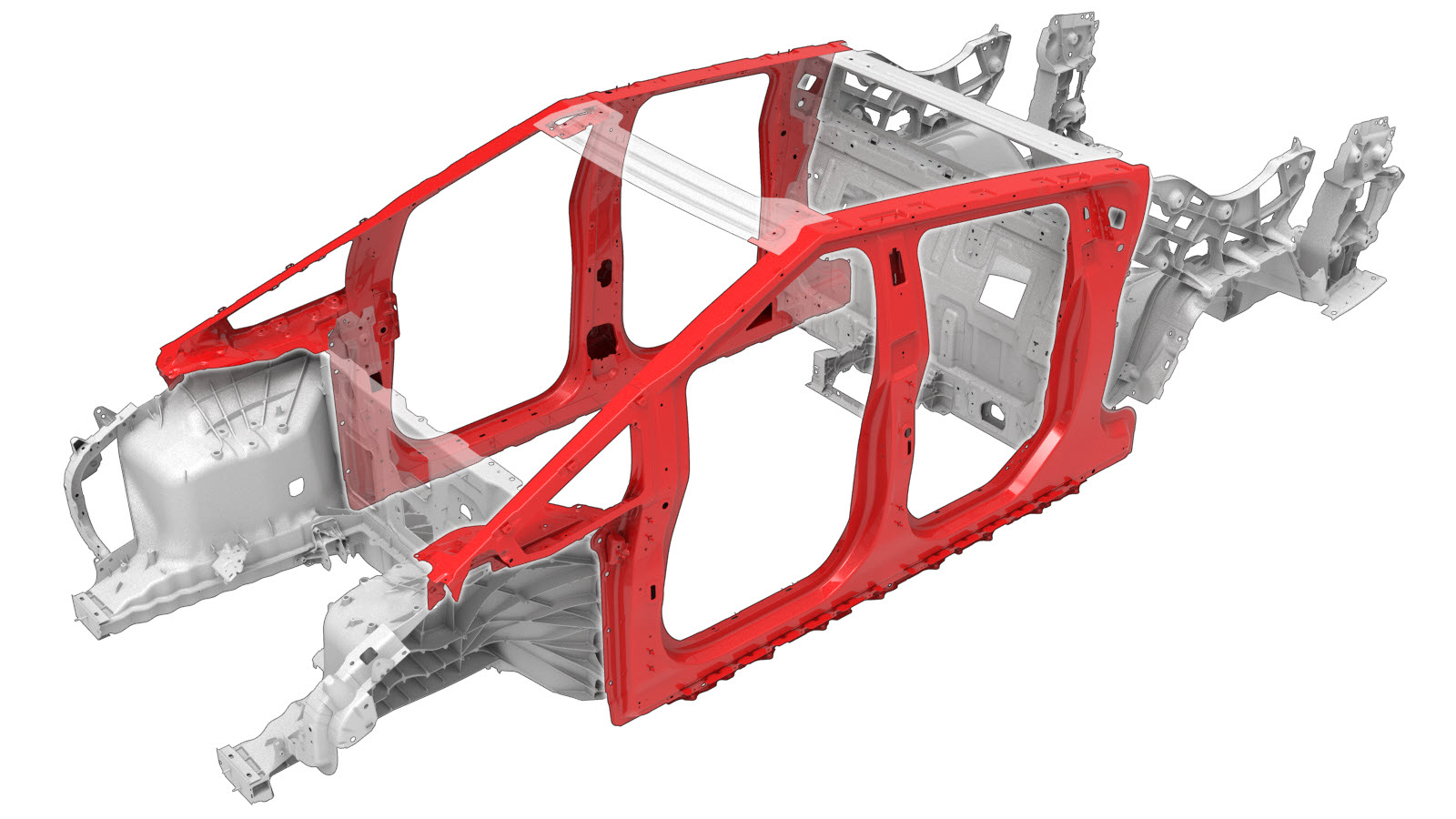
Côté de la carrosserie (complet)
 Code de correction :
10100101402
10100101602
REMARQUE : Sauf indication explicite dans la procédure, le code de correction ci-dessus inclut tous les travaux de réparation de collision requis pour effectuer cette procédure, y compris les procédures de réparation de collision connexes. N’appliquez pas plusieurs codes de correction de collision à la fois, à moins qu’il vous soit explicitement indiqué de le faire. Ajoutez toutes les procédures mécaniques connexes nécessaires pour effectuer cette procédure.
Code de correction :
10100101402
10100101602
REMARQUE : Sauf indication explicite dans la procédure, le code de correction ci-dessus inclut tous les travaux de réparation de collision requis pour effectuer cette procédure, y compris les procédures de réparation de collision connexes. N’appliquez pas plusieurs codes de correction de collision à la fois, à moins qu’il vous soit explicitement indiqué de le faire. Ajoutez toutes les procédures mécaniques connexes nécessaires pour effectuer cette procédure.
Informations relatives à la réparation
- Lisez attentivement toutes les pratiques générales et la documentation de sécurité relatives aux réparations après collision et enfilez un équipement de protection individuel (ÉPI) avant de commencer cette procédure.
- Installez sécuritairement le véhicule sur un banc de redressage pour effectuer cette procédure.
Liste des pièces
| Quantité | Description | Image/notes |
|---|---|---|
| 1 | ENS. CÔTÉ AVANT DE LA CARROSSERIE COMPLET (côté de la carrosserie - complet) | |
| 3 | BOUCHON |
Numéro de pièce Tesla 1870761-00. |
| 46 | Rivets de structure haute résistance, 6,5 mm | |
| 5 | Rivet à tête fraisée, 4,8 mm court | |
| 2 | Rivet à tête fraisée, 4,8 mm long | |
| 1 | Rivet fluotourné S08 | |
| 6 | Rivet fluotourné S18 | |
| 1 | Rivet fluotourné S28 | |
| 1 | Rivet fluotourné S48 | |
| 1 | Rivet fluotourné S58 | |
| 4 | Boulon , HF,M12x35,STL[109],ZNFL,PC | Numéro de pièce Tesla 1089657-00. |
| 4 | Boulon , HHL, M10x35, [109], G0110, CM | Numéro de pièce Tesla 1851387-00. |
| 5 | Boulon , HHL,M12x43 | Numéro de pièce Tesla 1882229-00. |
Lorsque vous commandez des pièces, consultez le Manuel des pièces et inscrivez le NIV du véhicule en réparation afin de trouver les bonnes pièces (et les numéros de pièce) pour le véhicule. Vous pouvez aussi utiliser la fonction de recherche dans le Manuel des pièces pour trouver une pièce précise pour le véhicule.
Procédure de réparation
-
Coupez le trou d'accès avant du composant original à l'aide du point central prémarqué.
.RemarqueUtilisez une scie-cloche à pointe de carbure de 1 1/8 pouce (29 mm) pour faire le trou.
Ligne de coupe
-
Sur le composant original, cherchez l'emplacement du point central du trou d'accès le plus à l'arrière.
Le point central du trou d'accès le plus à l'arrière devrait être situé à 155 mm de l'arrière du trou indiqué (mesure A).RemarqueSi le oint central marqué sur le composant est 150 mm, déplacez-le de 5 mm vers l'arrière de la marque (mesure B).Ligne/point de référence
- A = 155 mm.
- B = 5 mm
-
Sur le composant original, coupez les trous d'accès arrière.
Ligne de coupeRemarqueUtilisez une scie-cloche à pointe de carbure de 1 1/8 pouce (29 mm) pour faire les trous.
-
Sur la nouvelle pièce de rechange, coupez le trou d'accès avant à l'aide du point central prémarqué.
.RemarqueUtilisez une scie-cloche à pointe de carbure de 1 1/8 pouce (29 mm) pour faire le trou.
Ligne de coupe
-
Sur la nouvelle pièce de rechange, cherchez l'emplacement du point central du trou d'accès le plus à l'arrière.
Le point central du trou d'accès le plus à l'arrière devrait être situé à 155 mm de l'arrière du trou indiqué (mesure A).RemarqueSi le oint central marqué sur le composant est 150 mm, déplacez-le de 5 mm vers l'arrière de la marque (mesure B).Ligne/point de référence
- A = 155 mm
- B = 5 mm
-
Sur la nouvelle pièce de rechange, coupez les trous d'accès arrière.
Ligne de coupeRemarqueUtilisez une scie-cloche à pointe de carbure de 1 1/8 pouce (29 mm) pour faire les trous.
-
Retirez le composant d’origine.
ou Points de soudure d’usine
ou Rivets auto-perceurs d’usine
ou Percer à travers les points de soudure d’usineRemarqueLorsque vous percez dans les points de soudure, utilisez un foret qui permettra de créer un trou de la taille parfaite pour la fixation qui remplacera le point de soudure.ou Boulons
-
Préparation en vue de l’installation.
RemarqueUn X rouge indique un emplacement où une fixation installée en usine n’est pas remplacée.ou Rivets de structure haute résistance, 6,5 mm
- C = 49 mm
- D = 13 mm
ou Rivets à tête fraisée, 4,8 mm court
ou Rivets à tête fraisée, 4,8 mm long
ou Boulons
ou Points de soudure d’installation
- Appliquez de l’adhésif structural sur les surfaces de contact du véhicule et les nouveaux composants (le cas échéant).
-
Installez le ou les nouveaux composants.
Serrez les boulons au couple spécifié comme suit :
- Boulons HF,M12x35,STL[109],ZNFL,PC, numéro de pièce 1089657-00 : 90 Nm
- Boulons HHL, M10x35, numéro de pièce 1851387-00 : 90 Nm
- Boulons HHL,M12x435, numéro de pièce 1882229-00 : 67 Nm
-
Procédez au soudage par points par résistance.
ou Points de soudure d’installationAvertissementLe non-respect de toutes les mesures de sécurité, notamment l’utilisation de l’équipement de protection individuelle, peut entraîner des blessures graves ou des dommages matériels. Seuls les techniciens qui ont suivi la formation relative aux soudures approuvées de Tesla sont autorisés à souder des composants structuraux sur les véhicules Tesla.ATTENTIONN’effectuez pas de soudure sur un véhicule Tesla avant d’avoir fait la procédure d’isolation des véhicules électriques (rapportez-vous au Manuel d’entretien du véhicule en question pour en savoir plus sur la procédure). Le soudage sur un véhicule Tesla dont le circuit haute tension ou basse tension est alimenté peut endommager des composants du véhicule.
-
Installez les bouchons pour couvrir les trous d'accès.
RemarqueAppliquez du scellant pour joint au bas de chaque bouchon avant l'installation, puis retirez tout résidu de scellant de joint visible autour du côté extérieur du bouchon une fois l'installation terminée.
-
Ajustez l'arrière du renfort de marche du bas de caisse pour laisser un espace libre pour le bouchon couvrant le trou d'accès arrière.
RemarqueRetirez tout résidu de scellant pour joint autour des bouchons du trou d'accès se trouvant sous le joint en mousse du renfort de marche du bas de caisse.
Ligne de coupe
Ligne/point de référence
- D = 7 mm
- E = 32 mm.
- Effectuez toutes les opérations après réparation nécessaires.