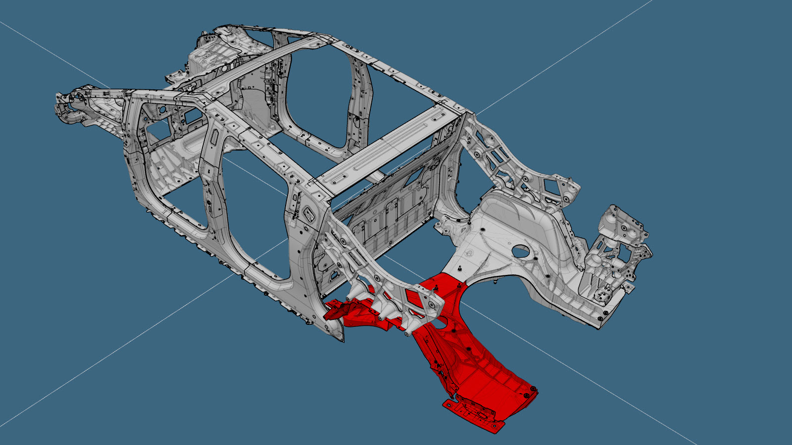
Bajos traseros de la carrocería (sección)
 Código de corrección:
10102001002
10102001102
NOTA: Salvo que se indique lo contrario explícitamente en el procedimiento, el código de corrección anterior refleja todo el trabajo de reparación de colisiones necesario para realizar este procedimiento, incluidos los procedimientos vinculados de reparación de colisiones. No acumule códigos de corrección de reparación de colisiones a menos que se le indique explícitamente que lo haga. Añada los procedimientos mecánicos asociados necesarios para llevar a cabo este procedimiento.
Código de corrección:
10102001002
10102001102
NOTA: Salvo que se indique lo contrario explícitamente en el procedimiento, el código de corrección anterior refleja todo el trabajo de reparación de colisiones necesario para realizar este procedimiento, incluidos los procedimientos vinculados de reparación de colisiones. No acumule códigos de corrección de reparación de colisiones a menos que se le indique explícitamente que lo haga. Añada los procedimientos mecánicos asociados necesarios para llevar a cabo este procedimiento.
Información de reparación
- Antes de iniciar este procedimiento, revise todas las prácticas generales y la documentación de seguridad de reparación de colisiones, y utilice el equipo de protección individual (EPI) adecuado.
- Monte correctamente el vehículo en un banco de bastidor para realizar este procedimiento.
- Los bajos traseros de la carrocería son un único componente y pueden sustituirse en una sola reparación como se describe en el procedimiento Bajos traseros de la carrocería (completos). Como alternativa, en lugar de sustituir el conjunto completo del mástil, se puede sustituir el lado izquierdo o derecho de los bajos traseros de la carrocería utilizando una pieza de servicio de la media sección de los bajos traseros y las placas de refuerzo superior e inferior, como se describe en Lista de piezas y en las instrucciones de Procedimiento de reparación.
Lista de piezas
| Cantidad | Descripción | Imagen / Notas |
|---|---|---|
| 1 | ASSEMBLY - REAR UNDER BODY HALF SECTION (media sección de los bajos traseros) | |
| 1 | ESTAMPADO SUPERIOR | |
| 1 | ESTAMPADO INFERIOR | |
| 2 | TAPÓN |
Referencia de Tesla 1870761-00. |
| 13 | Remache estructural de alta resistencia, 6,5 mm | |
| 4 | Remache de brida estructural | |
| 3 | Perno BLT,HHL,M10x33 | Referencia de Tesla 1851387-00. |
Al solicitar piezas, consulte el Catálogo de piezas e introduzca el VIN del vehículo que se va a reparar para encontrar las piezas correctas (y los números de pieza) para el vehículo. También puede utilizar la función de búsqueda del Catálogo de piezas para buscar una pieza específica para el vehículo.
Procedimiento de reparación
-
En el componente original, verifique la ubicación del punto central del orificio de acceso trasero.
El punto central del orificio de acceso trasero debería encontrarse a 155 mm de la parte trasera del orificio indicado (medición A).NotaSi el punto central marcado en el componente está a 150 mm, mueva el punto central 5 mm hacia la parte trasera del punto central marcado (medición B).Línea/punto de referencia
- A = 155 mm
- B = 5 mm
-
En el componente original, corte los orificios de acceso traseros.
Línea de corteNotaUtilice una sierra de corona con punta de carburo de 1 1/8 pulgadas (29 mm) para realizar los orificios.
-
Separe las secciones de los bajos traseros de la carrocería.
Corte junto a la línea de corte en relieve del lado dañado del componente.Línea de corteNotaSi los bajos traseros de la carrocería resultan dañados a ambos lados de la línea de corte en relieve, no se permite la división en secciones y deberá sustituirse el componente completo como se describe en el procedimiento Bajos traseros de la carrocería (completos).
-
Retire el componente original.
-
Corte y retire la pieza de fundición de los bajos traseros de la carrocería.
Corte los bajos traseros cerca del área interior del pilar C como se muestra y retire la parte cortada del componente original. (Retirar el material de fundición ayudará con el proceso de calentamiento y separación).NotaAl cortar cerca del interior del pilar C, corte únicamente en la zona marcada en color amarillo (no corte en la zona marcada en color rojo) para evitar dañar el interior del pilar C.
Línea de corte
-
Retire la parte restante del componente original.
Utilice métodos de separación y calor, y amole según sea necesario para retirar el material de fundición restante (mostrado en color rojo) cerca del área interior del pilar C.NotaTenga cuidado para asegurarse de no dañar el interior del pilar C al retirar la parte restante de la pieza fundida original de los bajos traseros.
-
Si ve la pestaña resaltada en rojo, retírela y lije el panel adecuadamente antes de continuar.
-
Preparación para la instalación.
Corte la parte restante del componente existente del vehículo para que encaje.NotaLa separación máxima entre los componentes nuevos y los existentes es de 3 mm.NotaUna X roja indica una ubicación en la que no se está sustituyendo una fijación instalada de fábrica.
o Remaches estructurales de alta resistencia, 6,5 mm
o Remaches de brida estructurales, 6,5 mm
o Pernos
- Aplique adhesivo estructural en las superficies de contacto del vehículo y en el nuevo componente o componentes.
-
Instale el componente o los componentes nuevos.
Apriete los pernos a 90 Nm.NotaRellene los huecos con adhesivo estructural.
-
Corte el refuerzo del escalón del estribo trasero para dejar espacio para el tapón que cubre el orificio de acceso trasero.
Línea de corte
Línea/punto de referencia
- C = 7 mm.
- D = 32 mm.
-
Coloque los tapones para cubrir los orificios de acceso.
NotaAplique sellador de juntas en la parte inferior de cada tapón antes de la instalación y retire cualquier sellador de juntas visible alrededor del borde exterior del tapón después de la instalación.NotaRetire cualquier sellador de juntas visible que haya alrededor de los tapones de los orificios de acceso, debajo de la junta de espuma del refuerzo del escalón del estribo trasero.
-
Instale Torre del portón trasero.
-
Instale Soporte de la defensa trasera.
-
Instale Soporte de referencia lateral.
- Efectúe las operaciones posteriores a la reparación necesarias.