Power Train - Remove for access
FRT No: 40012001
Remove
- Remove Power Electronics Module (PEM)
(refer to procedure).
- Raise vehicle on 2 post lift
(refer to procedure).
-
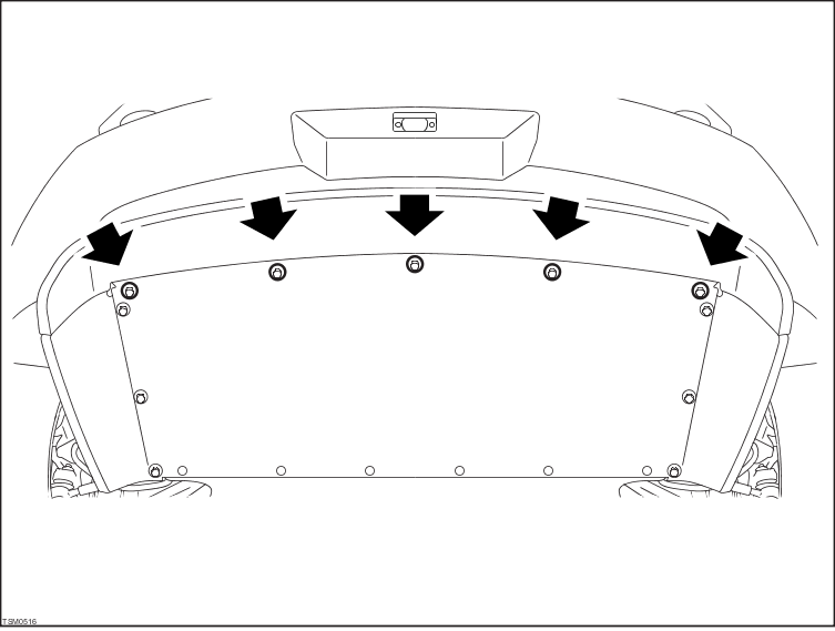
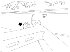
Remove bolts (x5) securing rear diffuser tray to rear diffuser trim (torque - 8 Nm).
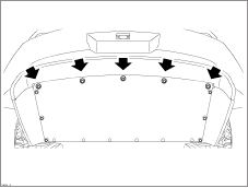
- Remove rear diffuser tray.
- Drain transmission fluid
(refer to procedure).
-
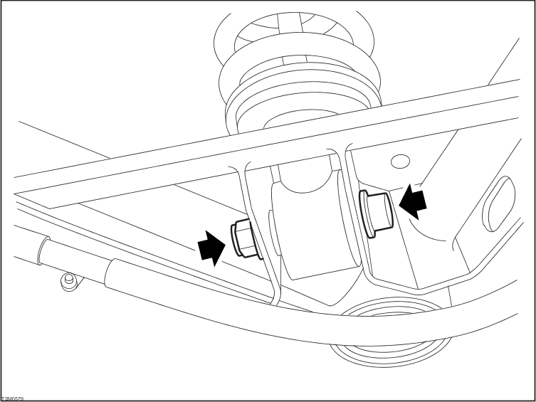
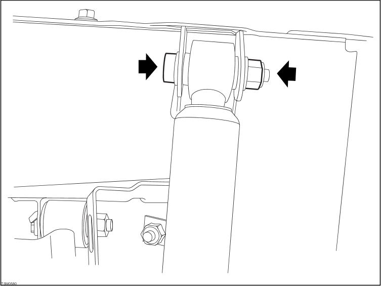
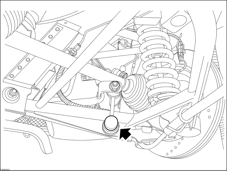
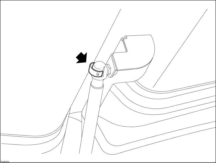
Remove Nyloc nut and bolt securing RH spring/damper assembly to lower wishbone (torque - 45 Nm).

- Remove Nyloc nut and bolt securing RH spring/damper assembly to chassis (torque - 45 Nm).
- Remove RH spring/damper assembly.
-
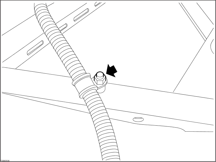
Remove nut securing brake hose P-clip to RH lower wishbone and release P-clip (torque - 9 Nm).
 | CAUTION: Ensure brake hose is aligned correctly with no excessive twist or bends. |

-
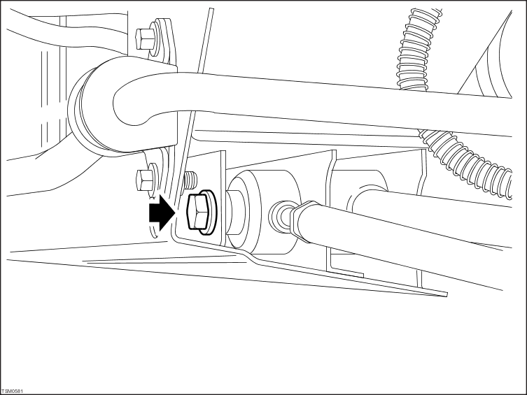
Remove nut securing RH sway bar link to wishbone and release link from wishbone (torque - 45 Nm).

-
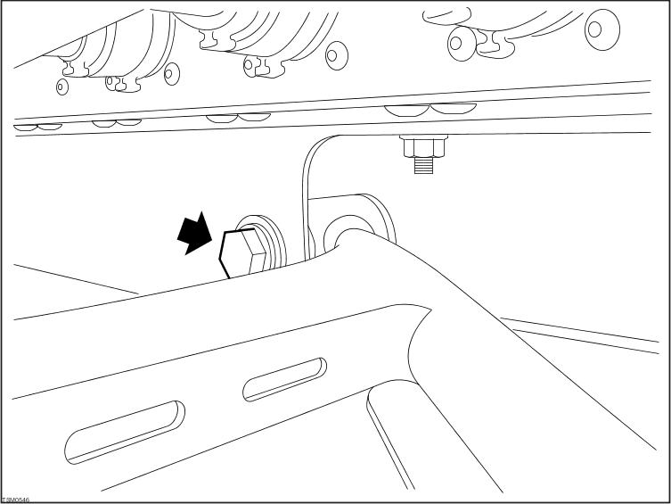
Remove bolt securing RH lower wishbone to cross member (torque - 45 Nm).
| CAUTION: Only tighten wishbone pivot bolts when the suspension is in ride height position. This can be achieved by either using the ride height tools or when the vehicle is on its wheels. |
-
Remove Nyloc nut and bolt securing RH lower wishbone/track control arm to subframe (torque - 60 Nm).
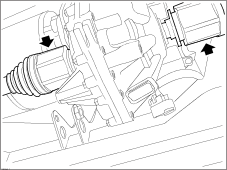
- Remove bolts (x2) securing motor cable to transmission (torque - 35 Nm). Release cable and allow to hang.
| CAUTION: Cover the motor cable connector using tool 1001017
to prevent damage/contamination. |
-
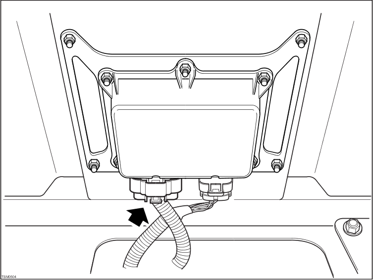
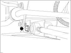
Disconnect harness connector from transmission control module and feed harness through opening in subframe (torque - 2 Nm).

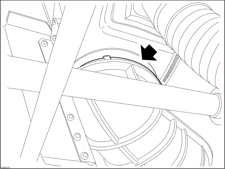
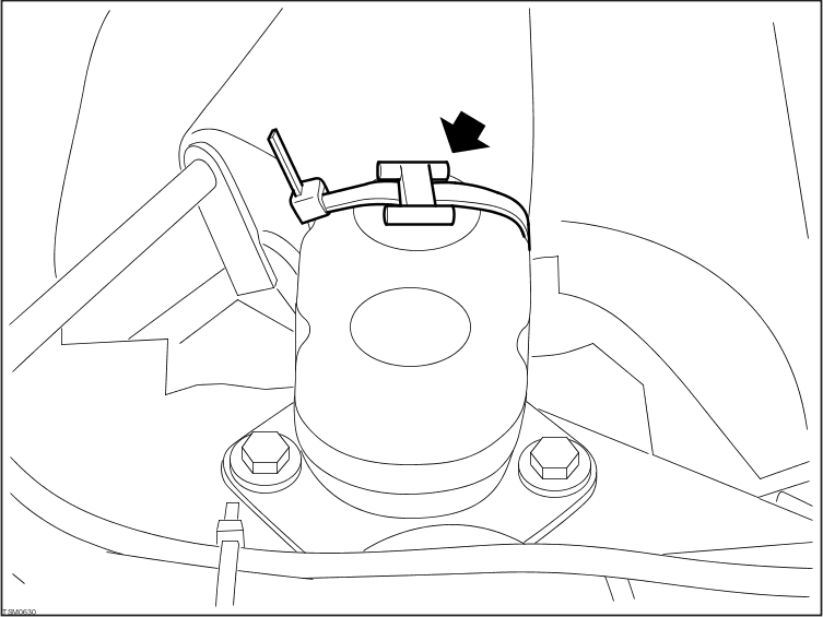
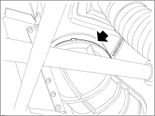
- Remove cable tie and release duct from lower motor shroud.
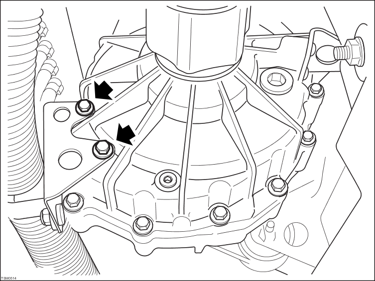
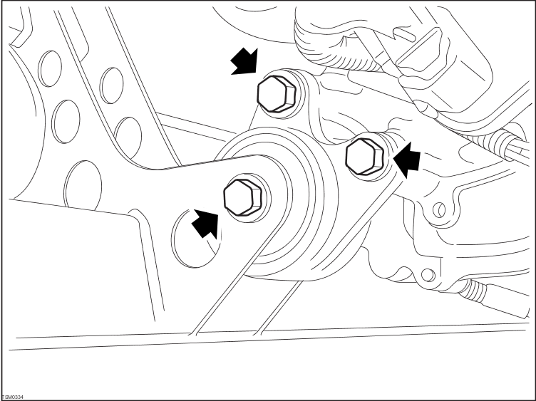
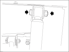
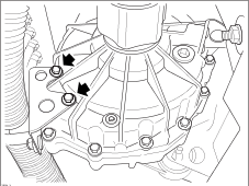
- Remove bolts (x2) securing mounting to transmission (torque - 35 Nm).
NOTE: When installing, apply Loctite® 242® thread locking compound to bolt/screw threads.

- Remove bolt securing mounting to subframe and remove mounting (torque - 80 Nm).
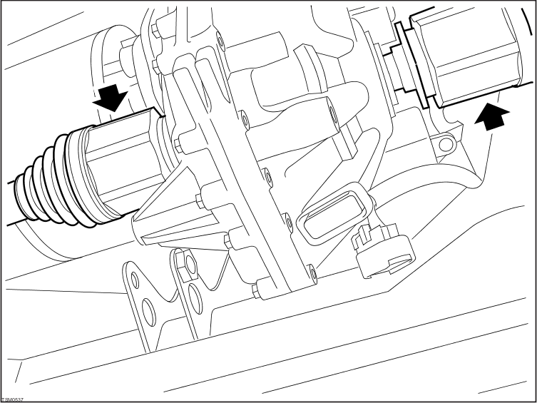
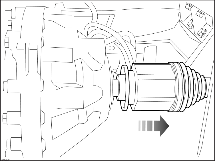
- Using tool 1000991, release both driveshafts from transmission.
NOTE: Place suitable absorbent material around the affected area to absorb any possible fluid spillage.
- Release RH lower wishbone from chassis and withdraw driveshaft from transmission. Position driveshaft aside.
| CAUTION: To avoid damage to the driveshaft oil seals, exercise caution when installing drive shafts into transmission. |
| CAUTION: Plug driveshaft apertures in transmission to prevent ingress of dirt or moisture. |
- Lower vehicle.
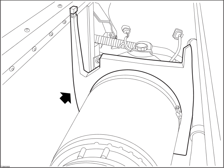
- Remove foam separator from around motor.
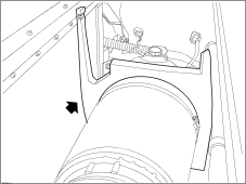
- Remove cable tie and fir tree fastener securing upper shroud to motor.

-
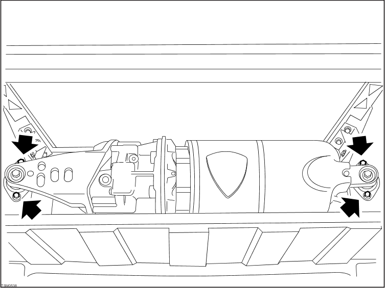
Remove bolts (x4) securing power train assembly to chassis (torque - 35 Nm).

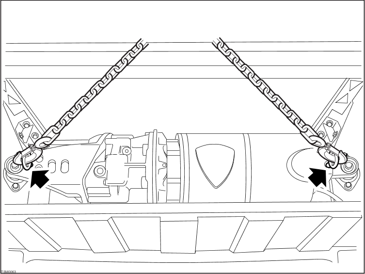
- Install lifting eyes (x2) to power train.
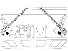
- Using suitable lifting equipment with load leveller, support weight of power train.
- Raise RH side power train approximately 20 mm for access.
- Disconnect LH driveshaft from transmission and position aside.
| CAUTION: To avoid damage to the driveshaft oil seals, exercise caution when installing drive shafts into transmission. |
| CAUTION: Plug driveshaft apertures in transmission to prevent ingress of dirt or moisture. |

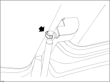
- With assistance, support trunk lid and release the clips securing the struts to the trunk lid. Disconnect struts and open trunk lid its to full extent.
- Insert protective material between power train and battery to protect battery casing.
- Raise power train assembly clear of trunk and remove assembly from vehicle.
Installation
- Installation procedure is reverse of removal except for the following.
| CAUTION: Replace all Nyloc nut(s). |
- Refill transmission with recommended fluid
(refer to procedure).