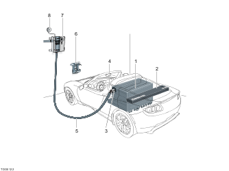
- Battery
- Power Electronics Module (PEM)
- Charge Connector (High Power Connector (HPC) or Mobile Charger (MC))
- Charge port
- Charging cable
- HPC bracket
- HPC
- Smoke detector (1st generation units only)
Charging System

As it is powered by electricity, the vehicle must be recharged on a regular basis. This is achieved by connecting the charge point on the vehicle to an external Alternating Current (AC) source.
The following three charging modes are supported:
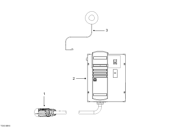
The HPC is the primary source for recharging the vehicle. The HPC features a charging cable terminated in a 4-pin charge connector and connects to the charge port on the vehicle during the charging process.
The purpose of the HPC is to ensure that the vehicle is charged safely using line voltage and it contains a switch which only connects line voltage to the vehicle when the conditions for charging have all been met.
A smoke detector may be connected to the HPC and, if triggered, will shut the charging unit down. The vehicle should be connected to the HPC whenever is not being used. This will ensure that the vehicle battery will be fully charged and the vehicle ready for use.
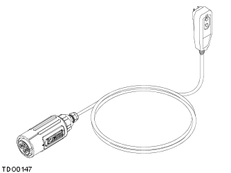
The mobile connector is available in 2 models, the MC120 (110V/120V) and the MC240 (220V/240V), every vehicle is supplied with an MC120. The mobile connector MC120/MC240 is designed to give the added flexibility of charging the vehicle while away from the HPC. Its small size means it can be carried in the trunk.
| WARNING: Incorrect usage could result in a fire, serious injury or even death. No attempt should be made to use, or modify, the mobile connector MC120/MC240 for use with any electrical outlet other than one which it has been designed for. |
NOTE: It will take longer to charge the vehicle using the mobile connector MC120/MC240 than when using the HPC.
Regenerative braking or regen is the conversion of the vehicle’s kinetic energy into electrical energy stored in the battery where it can be used to drive the vehicle.
The regen system is integrated within the motor and Power Electronics Module (PEM) and is designed to charge the battery whenever the vehicle is moving and the accelerator is not depressed. Regen generates an engine braking effect which slows the vehicle and feeds energy back to the battery where it can be used again.
For further information, refer to this information. .
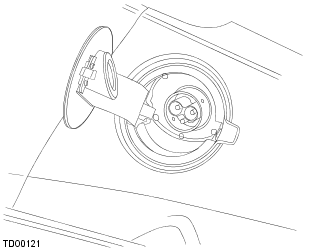
The vehicle features a 4 pin charge port on the LH rear side. The charge port is surrounded by a ring which illuminates in various colors depending on the charging state.
If the vehicle encounters a problem during charging, it will attempt to restart the process every hour if there is a charge failure. After three failed attempts, a fault will be set and the charge port ring will turn red. Unplug the cable and close the charge port door. This will clear the fault and allow charging to be restarted.
| Color | Charging state |
| White | Charge port door open; charge mode initiated |
| Blue | Connection between vehicle and High Power Connector successful |
| Blue (flashing) | Battery heating and cooling |
| Amber (flashing) | Charging in progress (flashes proportionately to the state-of-charge) |
| Green | Charging complete |
| Red | Fault detected |
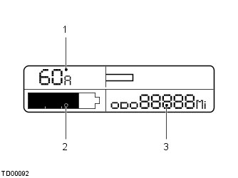
The ammeter, located in the instrument pack, displays information about the electrical current either entering or leaving the battery. The numbers at the top LH side of the Liquid Crystal Display (LCD) indicates the current flow in amps. The extending bar on the top right of the LCD indicates the amount of current by the length of the bar and also the direction the current is flowing.
Once a power supply is connected to the charge point, the vehicle uses the Power Electronics Module (PEM) and motor to convert Alternating Current (AC) power into Direct Current (DC) power which can then charge the battery.
| WARNING: DO NOT remove the cover on the HPC. The HPC is connected to a high voltage supply which could result in fire, serious injury or even death. |
| WARNING: Regularly, turn the power off at the control panel and inspect the charging cable and connector for signs of damage. |
During normal use, the HPC should be left on, even when the charging cable is not connected to the vehicle. The READY light on the control panel will illuminate green to indicate that the control panel is operating correctly. Although the HPC is on and ready, no voltage will be supplied until the charging cable is connected to the vehicle, and both the vehicle and HPC determine that it is safe for charging to begin.
Position the vehicle close to the HPC so that the charging cable easily reaches the charge port on the vehicle. Remove the key from the ignition switch, ensure the vehicle is in Park (P) and that the parking brake is engaged.
| CAUTION: Always charge the vehicle in a clean and dry environment. |
Open the charge port door on the LH side of the vehicle. This commands the PEM to prepare to charge, so it is critical that the switch on the door operates correctly. The HPC sends pilot signal which communicates the maximum allowable current. The ring around the charge port will illuminate white when the door is open.
If the charge port door is open but the charge cable is not connected, the light will extinguish if the APS turns off. The door will need to be closed and then opened to restart the charge process. To connect the charge cable to the vehicle:
| CAUTION: The connector end of the charge cable is heavy and may damage the paint work if dropped when connecting or disconnecting. |
The ring around the charge port will illuminate blue to indicate that the vehicle is communicating with the charging station. Once the vehicle has successfully communicated with the HPC, the READY light on the control panel will illuminate amber. If the key is in the ON position, the vehicle will not enter charging mode and the ring around the charge port will flash red.
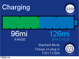
After a small delay, the vehicle will begin charging. The ring around the charge port will pulse amber and the READY light on the HPC will illuminate amber and begin flashing. A 'clunk' may be heard from the HPC when the contactors close and charging begins. This is normal and is not a cause for concern. Dependent upon the minimum/maximum brick temperature, pre-heating or pre-cooling of the battery may be required. This will be activated automatically when needed and can result in an extended delay before charging begins. For further information, refer to this information. The vehicle will begin charging at the default Standard charge unless another option has been selected using the touch screen. The vehicle uses the Power Electronics Module (PEM) and motor to convert AC voltage into DC voltage which is then fed into the battery. The PEM regulates the charging process and acts as the energy conversion device. It receives the AC power from the charge port and converts it into DC power to charge the battery by means of high frequency switching. The PEM also communicates with the HPC and Vehicle Management System (VMS) during the charging process. The HPC communicates a pilot signal to the PEM to determine how much current the PEM is allowed to draw. The charge status is displayed on the touch screen.
The VMS communicates the battery voltage limit and the maximum battery voltage to the PEM so the PEM can control the charge appropriately. It is possible for the user to manually reduce the amount of charging current.
The charge is controlled with feedback from internal voltage and current sensors in the PEM. The PEM ultimately decides when to stop charge and what the charge port LED should do. The frequency at which the ring around the charge port flashes will slow down as the charge level in the battery approaches full. While the vehicle is charging, the charge indicator on the instrument pack will flash.
The battery is the recipient of the DC power from the PEM. Although the PEM should stop charge when appropriate, the battery has internal circuitry and software that will prevent an overcharge situation. It may be necessary for the battery to be cooled while charging so the HVAC system may switch on. The battery is connected to the PEM via a short harness attached to the battery consisting of two power cables and two cables for the High Voltage Interlock Loop (HVIL). The HVIL will prevent high voltage from being exposed, by opening battery contactors, upon disconnecting the DC connector from the PEM.
The PEM does not communicate directly with the battery so the VMS relays critical information to the PEM during charge. The VMS also communicates to the PEM if the charge door is open, when to start charging and when to stop charging.
If the ring around the charge port illuminates red while charging, a fault has been detected. The charging process maybe stopped if the smoke detector detects any smoke in the area around the vehicle.
| CAUTION: If you detect any smoke or smell a burning acrid smell while charging, immediately turn off the power and exit the building. |
NOTE: A fault condition can be set by something as simple as a power outage. Try resetting the HPC to clear the fault.
When charging is complete, the ring around the charge port will stop flashing and then illuminate green.
To disconnect the charge cable from the vehicle:
The coolant heater, located inline with the coolant pipes to the battery, serves as a coolant heater and as a trickle charge resistor. If the battery is cold, temperature less than 37°F (3°C) and the HPC is connected to the vehicle, then the PEM will route, via the 3 pin connector located on the bottom LH side of the PEM, AC power to the heater so the battery will heat up before charging begins. Once the battery temperature is greater than 46°F (8°C) charging will start automatically.
The second scenario for heater resistor use is when trickle charge is required. Trickle charge is required when the battery charge level is low and the AC voltage being used to charge the vehicle is too high. In this case, the PEM will use the heater resistor to drop the AC voltage down and slowly bring the battery charge up to an acceptable level at which time normal charge will resume. For further information, refer to this information. .
The charge time is proportional to the amount of current and voltage provided by the charging system. Therefore, if the vehicle is being charged using the MCK, or the maximum current limit has been changed using the touch screen, the charging time will be longer.
The vehicle can be charged from a variety of AC voltages and currents. The time, in hours, it takes to charge the vehicle for the most common combinations of voltage, current and charge settings is shown in the tables below:
| Max. Current Available (A) | Storage Mode Charging Times in Hours | ||
| 120V | 208V | 240V | |
| 12 | 18 | 10.8 | 9.5 |
| 15 | N/A | N/A | N/A |
| 24 | N/A | 5.9 | 5.2 |
| 32 | N/A | 4.7 | 4.2 |
| 40 | N/A | 3.9 | 3.5 |
| 60 | N/A | 3.0 | 2.3 |
| 70 | N/A | 2.7 | 2.5 |
| Max. Current Available (A) | Standard Mode Charging Times in Hours | ||
| 120V | 208V | 240V | |
| 12 | 48 | 20.6 | 20 |
| 15 | 37 | N/A | N/A |
| 24 | N/A | 10.8 | 10 |
| 30 | N/A | N/A | 8 |
| 32 | N/A | 8.3 | 7.5 |
| 40 | N/A | 6.9 | 6 |
| 48 | N/A | N/A | N/A |
| 60 | N/A | 4.9 | 4.5 |
| 70 | N/A | 4.7 | 4 |
| Max. Current Available (A) | Range Mode Charging Times in Hours | ||
| 120V | 208V | 240V | |
| 12 | 54 | 23 | 22 |
| 15 | 41.5 | N/A | N/A |
| 24 | N/A | 12 | 11 |
| 32 | N/A | 9.3 | 8.5 |
| 40 | N/A | 7.6 | 7 |
| 48 | N/A | N/A | 6 |
| 60 | N/A | 5.4 | 5 |
| 70 | N/A | 5.2 | 4.5 |
NOTE: The time stated (hours) is the time to charge the battery from 10% to 100%.
NOTE: These times are estimates and vary dependant upon the internal impedance of the battery
The charging process can be stopped at any time by using the touch screen, and the charging cable can be left connected.
If the READY light or any of the fault warning indicators illuminate red, then a fault has been detected and vehicle charging will be terminated. Try to identify and fix the fault before resetting the HPC. Ground fault illuminates if a leak to ground is detected. Check the cable and connector for damage and ensure the HPC and vehicle are both dry. Disconnect the charging cable from the vehicle before pressing the ground fault reset and then the fault reset button.
The LEDs on the external smoke detector flash green during normal operation. If smoke is detected they will illuminate amber. Locate the source of the smoke before pressing the fault reset button.
Cable strain illuminates if the cable breaks away. Check if the break away panel on the underside of the HPC is dislodged and check the cable for any visible damage before pressing the fault reset button.
Charging fault illuminates if a general fault is detected while charging.
If the peak voltage of the AC line source is greater than 1.44 times greater the peak AC line voltage, the vehicle will enter a 'trickle charge' mode. This occurs when battery charge is very low or when the line voltage is high. Note that some neighborhoods have marginally higher line voltages than others and this mode may be entered slightly more often. To enter the mode, the vehicle will insert the battery coolant heater resistor in series with the AC source to decrease the voltage being delivered to the PEM. This mode is automatically entered by the vehicle and no additional action is required of the user or service personnel. During trickle charge a maximum of 7A will be drawn from the AC source regardless of maximum available current. Initially, charge will proceed much slower than usual due to the low current; however, once a sufficient pack voltage is reached, the vehicle will automatically exit trickle charge and enter standard charge. It is worth noting that to do this, the battery contactors must open and re-close. This action is normal. A side-effect of using the battery coolant heater resistor for Trickle Charge is that the pack will be heated during charge. At high ambient temperatures, charging may be prevented due to this phenomenon. In these scenarios, it is recommended that a MC120 cable be used to charge the car as the 120V cable will never require the vehicle to enter trickle charge mode. Due to the unique nature of the charge circuits, charging will actually proceed much faster using a MC120 rather than a higher voltage option in scenarios when trickle charge is required.
Slow charge occurs when charging an battery within the vehicle via the onboard charger (i.e. the PEM) but at a reduced rate because minimum brick voltage is below 3V. Slow charging should be conducted at less than 15A DC and for no more than 90 minutes (assuming 15A). If after 90 minutes, minimum brick voltage is not above 3V, there may be a problem with a cell. Slow charge will continue until minimum brick voltage is some threshold above 3V at which point the vehicle will automatically transition to normal charge.
The battery current is different than the line current displayed on the touch screen; therefore, the touch screen may display some line current value above 15A. As trickle charge supersedes slow charge, there may be times when the minimum brick voltage is below 3V but the AC line voltage is sufficiently higher than the pack voltage and trickle charge is required. The vehicle will automatically enter trickle charge, transition to slow charge, and upon the voltage rising high enough, transition into standard charge.
NOTE: Trickle charge and slow charge conditions may exist at the same time when both the line voltage is high and brick voltage is below 3V. When this happens, the vehicle will enter trickle charge until the line voltage is high enough. It will then exit charge, and if brick voltage is still below 3V, it will enter slow charge.
| WARNING: Always ensure that the mobile connector MC120/MC240 is located in a clean and dry area during use. |
| WARNING: Never use an extension cable with the mobile connector MC120/MC240. Using an extension cable could result in a fire. |
| WARNING: Ensure that the charging cable is located so as not to cause an obstruction to pedestrians or be damaged by other vehicles. |
| CAUTION: If you are charging your vehicle outside, remember to lock the vehicle before leaving it. The charge port illumination will switch off but the vehicle will continue to charge with the security system activated. |
NOTE: If the electrical outlet is unable to provide the current demanded by the mobile connector MC120/MC240, the circuit breaker protecting the electrical outlet may trip. If this happens, it will be necessary to reduce the maximum current limit via the touch screen.
NOTE: There is no LED on the MC120.
The charge process operates in the same way as when the vehicle is connected to the HPC. Use the same procedure for disconnecting the charging cable as you would when using the HPC.
If the battery voltage increases above or drops below the set thresholds, battery recovery procedures must be performed. For further information, refer to this information. .
When the charging connector is connected to the vehicle, the touch screen will enter the charging mode. The following screens are available in this mode:
This screen displays the estimated vehicle range and the remaining vehicle charge.
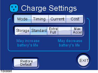
This screen displays the selected charging mode. Standard is the default setting and Storage, Range and Performance are alternatives.
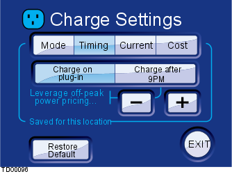
This screen displays the options of when to charge the vehicle. The Restore Default button resets the settings back to the factory defaults.
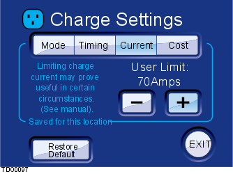
This screen displays the option to increase or decrease the charge current to protect home wiring. The Restore Default button resets the settings back to the factory defaults.
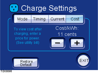
This screen displays the option to increase or decrease the cost per energy unit allowing energy costs to be tracked. The Restore Default button resets the settings back to the factory defaults.
Once connected to the HPC or MC120/MC240, several different charging modes are available. The charging modes can be selected via the touch screen. These different modes change the driving characteristics of the vehicle. If no option is selected, the vehicle will always default to the Standard charge mode and maximum possible current limit.
The default charging mode. This mode provides optimum balance between range, performance and cell longevity.
This mode charges the cells within the battery to their maximum subsequently extending the operating range for the vehicle.
| CAUTION: Repeated use of the Maximum Range mode will reduce the lifetime of the cells within the battery. |
To preserve the life of the battery, this charging mode will be cancelled automatically after 72 hours or after the vehicle has been driven more than 0.1 miles.
If the vehicle is not be driven for more than two weeks, the vehicle is connected to the HPC and Storage mode is selected using the touch screen. In this mode, the vehicle will 'wake up' every 24 hours and if necessary restart charging to top-up the battery charge level. This mode charges the cells within the battery to a reduced level while maintaining the integrity of the vehicle's electronic systems such as the security system. If it is not possible to leave the vehicle connected to the HPC, the vehicle should be fully charged before being left. Ideally it should then be checked every 10 days and charged as necessary. This charging mode will be cancelled automatically once the vehicle has been driven more than five miles.
| CAUTION: Permanent damage to the battery may be caused if the charge level is allowed to fall too low. If you leave the vehicle for an extended period between uses, the battery will slowly lose its charge. If the charge level is allowed to fall to a critically low level, it may be impossible to charge the vehicle using the HPC or MCK. |
NOTE: If the vehicle is driven after being charged in Storage mode, the range and performance of the vehicle will be reduced. This is temporary and will return to normal after the vehicle has been charged in Standard mode.