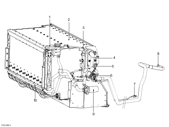
- Coolant expansion tank
- Battery
- Air bleed pipe
- Heat exchanger
- Coolant heater (in pipe)
- Thermal Expansion Valve (TXV)
- Liquid refrigerant feed pipe
- Refrigerant vapor return pipe
- Coolant pump
- Coolant manifold
Battery Cooling

The purpose of the battery cooling system is to prevent the pack from temperature extremes both hot and cold and to maintain the mean temperature between specified limits. The components are located mainly on the RH bodyside.
The following lists all the components that are shared with the passenger compartment Heating, Ventilation Air Conditioning (HVAC) system.
For further information, refer to this information.
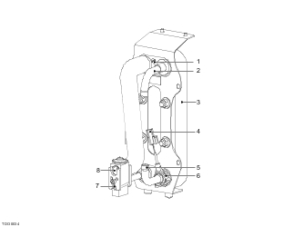
The unit is located on the RH side of the battery and is attached by studs and nuts to a bracket which is mounted on four rubber isolation bushes.
Battery Coolant Reservoir Assembly
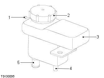
The coolant reservoir maintains a reserve of coolant to allow for expansion and contraction of the coolant level. It is mounted at the RH rear of the vehicle and provides an air bleed return from the coolant inlet to the battery heat exchanger preventing any bubbles becoming trapped in the system.
Battery Coolant (Glycol) Temperature Sensor
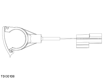
The battery coolant temperature sensor is located on the outlet of the heat exchanger. It comprises a split plastic sensor which clips around the heat exchanger outlet pipe and a connector which connects to the 12V controller. This sensor measures the temperature of the coolant as it leaves the heat exchanger.
Battery Coolant Heater (in pipe)
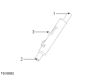
The battery coolant heater is located on the RH side of the battery between the heat exchanger and the coolant pump.
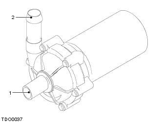
The battery coolant pump is a rotary type pump located on the RH rear of the vehicle.
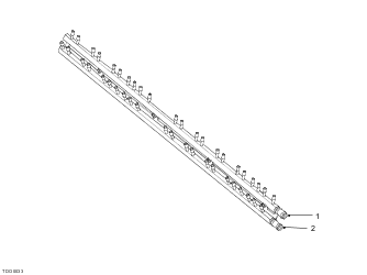
The battery manifold, located under the battery, consists of two parallel pipes: an inlet and an outlet, each with 22 stubs. Both the inlet and the outlet pipes are closed at the LH end. Nipples on the manifold direct two separate coolant streams through flexible pipes to each of the battery sheets.
Battery Humidity and Immersion Sensors
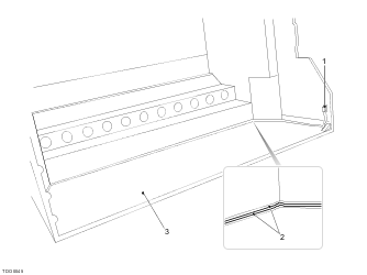
The immersion sensor is constructed from two metal strips that lay parallel to each other and are embedded in a plastic material. The sensor runs inside the base of the battery enclosure and connects to the BSM.
Within the BSM is a humidity sensor (not illustrated) which is used to monitor the detect excessive moisture in the battery.
As the battery is charged or discharged, heat is generated within the cells. The Battery Monitor Board (BMB) is integrated into each sheet of the battery comprising of a voltage and temperature monitoring Printed Circuit Board (PCB). The BMB measures voltage at each of the 9 bricks within a sheet, making for 99 BMB voltage measurements across the battery. A BMB measures temperature in six strategic locations within a sheet, making for 66 BMB temperature measurements across the battery. The Battery Safety Monitor (BSM) is a single PCB in the battery containing small microprocessors that monitor and control battery behavior.
To operate effectively, the battery must be between -4°F (‑20°C) and +122°F (+50°C) for powering the vehicle’s systems and between 32°F (0°C) and 113°F (45°C) during charging. A cooling system is built into the battery and an external electric pump circulates coolant to maintain the correct temperature. A heater is incorporated into the system to ensure the temperature is above the minimum before charging and a heat exchanger transfers excess heat from the coolant to the Air Conditioning (A/C) system when required. Coolant flow from the pump is adjusted by the 12V controller depending on the signals from the battery temperature and humidity sensors.
The VMS constantly monitors the battery coolant temperature. Cooling may be initiated, via the 12V controller, when the vehicle is parked, for example while charging. If the battery temperature exceeds specified limits, the 12V controller increases coolant flow and, if necessary, switches on the A/C compressor and operates the battery refrigerant solenoid valve to divert refrigerant through the heat exchanger for additional cooling. When the temperature of the coolant falls below 46°F (8°C) it switches off the flow of refrigerant to prevent over cooling. It will not restore refrigerant flow until the temperature has risen above 54°F (12°C).
The VMS determines the correct balance of cabin and battery cooling. It achieves this by varying the flow rate of the battery coolant by or diverting refrigerant through the battery heat exchanger if the battery coolant requires additional cooling.
The battery cooling system connects to the battery module via a pair of manifold pipes and has two modes of operation:
The battery charging temperature range is between 37°F (3°C) and 113°F (45°C). The temperature is sensed within the battery by the internal temperature probes. An electric coolant heater is installed inline between the coolant pump and the heat exchanger.
The coolant heater is only activated to raise the internal temperature the battery above 46°F (8°C) before charging commences and will only activate if the charge port door is open. The coolant heater will not operate under any other conditions apart from charging. The coolant heater is only powered by an external AC voltage power source, not from the battery.
The coolant heater takes a 110V feed from the Power Electronics Module (PEM) which is in turn taking it from the line voltage from the High Power Connector (HPC) or MC120/MC240. The coolant pump is always active while charging commanded by the 12V controller and this circulates the warmed coolant to the battery.
If water droplets bridge the two metal strips of the immersion sensor, charging using a mobile connector MC240 is prevented. The sensor is useful to service to diagnose a leak in the battery enclosure.
The BSM uses the humidity sensor to calculate the dew point of the coolant tubes inside the battery and help calculate cooling in the pack to prevent condensation and excessive moisture inside the pack. If the battery internals reach the dew point and there is a risk of condensation within the unit, the humidity sensor will signal the Vehicle Management System (VMS) to stop battery cooling.
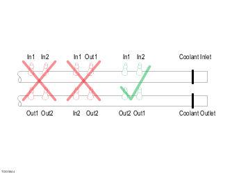
The inlet manifold pipe takes in coolant from the pump via the battery coolant heater and heat exchanger. Stubs on the manifold direct two separate coolant streams through flexible pipes to each of the battery sheets. On the outlet manifold pipe, two corresponding stubs and flexible pipes collect the returning coolant from each sheet and direct it through the outlet pipe to the pump.
Within the battery sheet, each brick has two coolant streams, which flow in opposite directions. This maintains a uniform temperature throughout the whole unit. The VMS monitors the battery temperature and determines the cooling required, varying the rate of flow accordingly. The coolant pump always operates during drive, charge or if the battery state-of-charge is over 90%.
For each sheet, the flexible inlet and outlet hoses to the stubs should be connected in diagonally opposite pairs. This ensures the correct reverse flow of coolant through the battery.
| CAUTION: Incorrect connections to the manifold will reduce the efficiency of the battery cooling system and may result in damage to and/or reduced performance of the battery. |
If the coolant flow is already at its highest rate and the battery temperature sensors record a maximum temperature above the thresholds listed in the table below, the VMS will demand additional cooling from the 12V controller.
The 12V controller will start the compressor and open the battery refrigerant solenoid valve, allowing liquid refrigerant through to the battery heat exchanger where it absorbs heat from the coolant.
Heat from the battery is transferred through the inner chamber walls of the heat exchanger to the refrigerant which then returns to the compressor. Heat is removed with airflow though the condenser with the air of the condenser fans.
When the battery temperature rises, the coolant strategy is as follows:
| Battery Temperature °F (°C) | Cooling Strategy |
| 62 (17) | Drive Max. Range Mode HVAC compressor enabled to 100% |
| 77 (25) | Charge Storage and Charge Standard Modes HVAC compressor enabled to 100% |
| 95 (35) | Drive Storage and Drive Standard Modes HVAC compressor enabled to 75% and battery refrigerant solenoid opened |
| 104 (40) | Drive Max. Range and Drive Max. Performance Modes HVAC compressor enabled to 75% |
| 104 (40) | Charge Max, Performance Modes HVAC compressor enabled to 100% |
| 104 (40) | 120V MC120 Charging HVAC compressor enabled to 100% |
| 113 (45) | HVAC compressor enabled to 100% and power limited to 50% |
| 116 (47) | Regenerative braking disabled |
| 122 (50) | Power limited to 50% |
| 129 (54) | Battery contactors opened. All high voltage disabled and contained within the battery |
As the battery temperature falls, the coolant strategy is as follows:
| Battery Temperature °F (°C) | Cooling Strategy |
| 122 (50) | Battery contactors closed. Power is limited to 50% at temperatures up to 122 °F (50°C) |
| 113 (45) | Power is not limited at temperatures up to 113 °F (45°C) |
| 113 (45) | Regenerative braking enabled |
| 104 (40) | HVAC compressor enabled to 75% (down from 100%) |
| 98 (37) | Drive Max. Range and Drive Max, Performance Modes HVAC compressor disabled |
| 98 (37) | 120V MC120 Charging HVAC compressor disabled |
| 95 (35) | Charge Max, Performance Modes HVAC compressor disabled |
| 86 (30) | Drive Storage and Drive Standard Modes HVAC compressor disabled |
| 77 (25) | HVAC battery refrigerant solenoid closed |
| 68 (20) | Charge Storage and Charge Standard Modes HVAC compressor disabled |
| 59 (15) | Drive Max. Range Mode HVAC compressor disable |