The vehicle is fitted with four braking systems:
- A hydraulically operated friction braking system with a supplemental Anti-lock Braking System (ABS) operates on all four wheels;
- A mechanically operated friction brake provides a parking function which operates on the rear wheels only;
- An electrically operated parking pawl mechanism operates on the transmission to lock the rear wheels;
- The electric motor provides regenerative braking to the rear driven wheels on the overrun. This causes the motor, whilst slowing the vehicle, to act as a generator which charges the battery.
The braking system is a hydraulically operated system with ventilated discs all round. Twin piston aluminum alloy calipers act on the front discs and single piston aluminum alloy calipers on the rear. A mechanical parking brake function is operated by a parking lever mounted on the passenger seat frame. An electrically powered pump provides vacuum to a servo which assists the operation of a tandem master cylinder. Fluid from the master cylinder flows through front/rear split hydraulic circuits to the calipers via the ABS modulator and a combination of solid and flexible pipes.
The regenerative braking available can produce a similar braking effect to a gasoline engined cars with manual transmission. Sensible driving, which predicts braking requirements and avoids the need for “panic braking” using the friction brakes, will significantly increase the driving range of the vehicle. For further information, refer to this information.
The vehicle is fitted with twin hydraulic circuits. The lower portion of the fluid reservoir has a separator which divides the fluid into two chambers. Each chamber feeds fluid to one circuit so that, in the event of fluid loss from one circuit, the other circuit would continue to operate normally. This will provide some braking effect although it will be less effective than with both circuits operational. Symptoms of single circuit failure include increased stopping distances and pedal travel when the brakes are operated.
| WARNING: DO NOT continue to drive a vehicle with one failed hydraulic circuit: braking will be severely reduced. The twin circuit design has been devised to provide an emergency backup only. In the event of circuit failure, stop the vehicle as safely as possible and repair the problem before continuing to drive. |
The pedal box is fitted under the dash board and is secured to the body tub. An offset crank arm on the brake pedal pivot connects the pedal to the servo input pushrod. The two components are linked by a clevis pin which is held in place by a split pin.
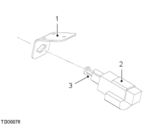
- Switch bracket
- Switch
- Plunger
The brake light switch bracket is riveted to the pedal box and provides a bayonet socket into which the switch can be inserted. Rotating the switch 90° clockwise locks the switch in position. A four-pin harness connector provides a 12V feed and earth path (two of the pins are redundant).
The switch consists of a casing, a spring loaded plunger and two contacts. The end of the plunger rests against the back of the brake pedal which holds the plunger in against the spring pressure. As the pedal is depressed, the plunger is forced out. If pedal movement is sufficient, the plunger will close the switch contacts, completing the circuit and illuminating the brake lights. The same circuit is monitored by the ABS and cruise control systems.
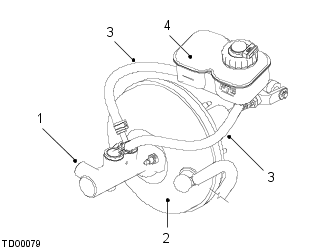
- Master cylinder
- Servo
- Brake fluid transfer pipes
- Brake fluid reservoir incorporating cap and level switch
Brake Fluid Reservoir and Low Level Fluid Sensor
The brake fluid reservoir is mounted remotely from the master cylinder to allow clearance for the hood. Two rubber hoses connect the reservoir to each side of the master cylinder using push fit connections and spring clips.
The translucent plastic brake fluid reservoir allows the brake fluid level to be checked using the level markings on the outer surface. A fluid level switch is incorporated into the reservoir cap which is screwed onto the top of the brake fluid reservoir. The assembly comprises of electrical contacts, a plunger, a float and a flexible grommet.
The brake master cylinder is a non-serviceable conventional tandem type unit mounted onto the front face of the servo on two studs and secured with nuts. Two internal pistons separate the independent front and rear brake circuits. Two larger diameter pipes transfer brake fluid from the master cylinder to the ABS modulator.
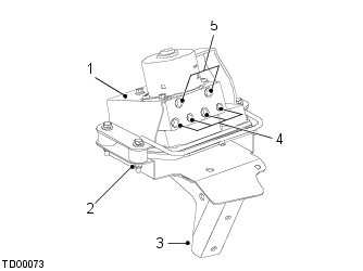
- ABS modulator
- Mounting rubber
- Mounting bracket
- Outlet ports
- Inlet ports
The ABS modulator is a non-serviceable unit consisting of an integrated hydraulic modulator and ABS ECU. The modulator, fitted on rubber mounts on the front LH side under the hood, is fed via two brake pipes, one from either side of the split master cylinder. Four brake pipes exit the valve block and feed through to each brake caliper.
The brake servo assembly is of a standard, suspended vacuum, single diaphragm type fitted to the body secured with three nuts. The circular housing contains diaphragms, a driving piston, a control valve assembly, input and output push rods and a non-serviceable filter. The input push rod is connected to the brake pedal and passes through the driving piston to the control valve assembly. The output push rod locates in the primary piston of the master cylinder. A port in the front face of the servo housing is connected to a vacuum line from the vacuum pump via an elbow joint. A non-return valve is incorporated into the elbow joint.
Throughout the vehicle, solid 0.186 in (4.76 mm) brake pipe is used, secured to the body using clips. The flared pipe ends are fitted with metric unions which mate with conical seats machined into components. Brake pipes run along the LH and RH bodysides to each rear brake.
Flexible rubber hoses connect the solid brake pipes to the brake calipers. Steel spiral wrap is fitted to the brake hoses to prevent chafing against suspension components. The brake hoses are secured to the upper wishbones at the front using a single threaded stub and the lower wishbones using a single threaded stub at the rear.
| Description | Specification |
| Brake fluid | Any brand of DOT 4 brake or brake/clutch fluid |
| Capacity (fill from dry) | 1.6 quart (US)/1.5 l |
DOT 4 brake fluid is specified for use in the hydraulic braking circuit. DOT 4 brake fluid is an incompressible glycol based fluid and is used to transfer brake pressure from the master cylinder through the brake pipes to the brake calipers. Brake applications generate heat energy which is transferred into the braking components. Therefore brake fluid must have a high boiling point to remain efficient. Brake fluid is hygroscopic, meaning that it absorbs moisture from the atmosphere. The dry boiling point of brake fluid, when new, is 446°F (230°C); the wet boiling point of brake fluid, that is when it is in use and has absorbed moisture from the atmosphere, is 311°F (155°C). If the brake fluid boils, compressible gas bubbles form resulting in a longer pedal travel, potentially reducing braking effect. This is one of the causes of brake pedal fade.
| CAUTION: DO NOT use fluid from unsealed containers as it may have absorbed moisture from the atmosphere. |
It is essential that the correct specification of brake fluid is used. Incorrect specification brake fluid can cause damage to the seals within the hydraulic system and lead to brake failure.
| CAUTION: DO NOT use synthetic brake fluid. |
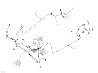
- RH front flexible brake hose
- RH bodyside brake pipe
- RH brake pipe to RH rear flexible hose
- RH rear flexible brake hose
- LH rear flexible brake hose
- LH brake pipe to LH rear flexible brake hose
- LH bodyside brake pipe
- LH front flexible brake hose
- Brake pipe – ABS modulator to LH bodyside brake pipe
- Brake pipe – ABS modulator to LH front flexible brake hose
- Brake pipe – master cylinder (rear) to ABS modulator
- Brake pipe – master cylinder (front) to ABS modulator
- Brake pipe – ABS modulator to RH bodyside brake pipe
- Brake pipe – ABS modulator to RH front flexible brake hose
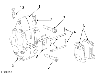
- Brake caliper body
- Flexible brake hose union
- Bolt M10 x65
- R-clips (x2)
- Brake pads (x2)
- Bolt M10 x80
- Retaining pins (x2)
- Anti-rattle spring plate (directional)
- Link pipe
- Bleed nipple and dust cap
The front calipers are of fixed design and are constructed from two steel bodies secured together using four bolts. They are radial mount calipers secured to the rear of the forged suspension upright using two bolts. Each caliper incorporates two pistons hydraulically connected using a link pipe. A seal at the outer end of each piston prevents the piston, seal and bore becoming contaminated, damaged or corroded by road dirt. A single bleed nipple and dust cap is fitted on the outside face of the caliper.
Within each piston bore, a specially shaped groove is machined to provide a recess for the hydraulic seals. These have several functions:
- To prevent the loss of brake fluid past the piston;
- To lightly grip the exterior surface of the piston as it is pushed outward during braking, causing the seal to deform and store energy;
- To use the stored energy of deformation to retract the piston when the brakes are released, reducing friction between the pads and discs;
- To allow the pistons to slide further out of the bore when piston movement is excessive, compensating for any wear in the pads and providing an automatic adjustment of the brakes.
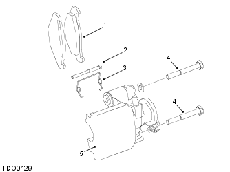
- Brake pads (x2)
- Brake pad retaining pin
- Anti-rattle spring
- Bolt M8 x60
- Brake caliper body
The rear calipers are of floating type and are constructed from steel mounted on the rear upright using two bolts. Each caliper incorporates a single piston. A seal at the outer end of the piston prevents the piston, seal and bore becoming contaminated, damaged or corroded by road dirt. A single bleed nipple is fitted on the outside face of the caliper.
The calipers feature an integral parking brake mechanism connected to the parking brake cables via steel eyelets. The calipers feature a pair of steel discs featuring machined ramps. Ball bearings locate in the ramps.
| Description | Specification (Front) | Specification (Rear) |
| Disc diameter | 11.81 in (300 mm) | 12.20 in (310 mm) |
| Disc thickness – new | 1.02 in (26 mm) | 1.02 in (26 mm) |
| Disc thickness – service limit | 0.98 in (24.9 mm) | 0.98 in (24.9 mm) |
Both front and rear brake discs are handed rotors of cast iron construction with a ventilated design and are fitted to the hub bearing drive flange secured by a single countersunk screw.
The ventilation openings all face forwards to improve the internal flow of air through the curved cooling vanes. Cross drillings in the discs reduce the amount the pad faces harden or 'glaze' in use. Over the life of the pads this gives a more consistent braking effect as the friction surfaces wear since glazed pads have a reduced coefficient of friction. The drillings also prevent the build up of gas between the brake pads and discs, which can contribute to brake fade during prolonged or heavy braking.
Re-surfacing of the brakes discs is not permitted and discs must be renewed in axle pairs in the event of excessive runout, scoring, ridges in the braking surface, cracking or corrosion.
| Description | Specification (Front) | Specification (Rear) |
| Brake pad thickness, excluding back plate – new | 0.354 in (9 mm) | 0.256 in (6.5 mm) |
| Brake pad thickness, excluding back plate – service limit | 0.098 in (2.5 mm) | 0.098 in (2.5 mm) |
The front and rear brake pads are manufactured from both lead and asbestos free materials.
The front pads are retained in the caliper body using two retaining pins and a directional anti-rattle plate to reduce brake pad squeal. Each half of the caliper body has recesses on the inner faces to locate the brake pads.
The rear brake pads are retained by a single retaining pin in the caliper body. An anti-rattle spring is also fitted to the rear caliper.
NOTE: Apply a light coating of any proprietary brand of high temperature copper anti-seize paste to the contact area between the pad and caliper piston.
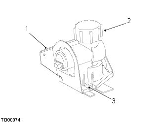
- Mounting bracket
- Vacuum pump
- Mounting rubber
With gasoline internal combustion engines, a vacuum forms in the inlet manifold which can be utilised by the servo to provide brake pedal assistance. On electrically powered vehicles no inlet vacuum is produced therefore an electrically powered vacuum pump is used.
The pump assembly non-serviceable unit encased in a hard plastic outer casing which is totally enclosed in a rigid NVH (Noise, Vibration and Harshness) package and mounted to a bracket via three rubber isolators. The complete assembly and bracket is then bolted to the crash structure under the LH inner wing liner. The pump consists of an electric motor which drives two vertically opposed pistons and diaphragms to provide improved balance and reduced vibration. Both pumping chambers are linked by a single tube and air is drawn from the servo through a fibre reinforced rubber hose which prevents collapse due to atmospheric pressure. Non-return valves are fitted to each chamber to prevent leakage. The pumped air is exhausted through a machined exit port via a non-serviceable gauze filter.
The motor is continuously powered by a 12V supply from the switchpack with the key in the ON position and is controlled by dedicated sensors independent of the vehicle's ECUs. The two sensors are mounted onto a Printed Circuit Board (PCB) which is mounted onto the outside of the pump's lower vacuum chamber. The pressure sensing bulbs extend through machined holes into the lower pressure chamber to measure vacuum directly. They are sealed in place with an O-ring to prevent leakage. The maximum vacuum sensor switches power off if a pre-determined level of vacuum is exceeded; the pressure switch starts the pump if vacuum is insufficient.
The wheel speed sensors are active sensors (i.e. they receive a power feed from the ABS ECU) that supply the ABS modulator with wheel speed signals. A wheel speed sensor is installed in each wheel bearing unit in close proximity to the inboard seal. The seals, which rotate with the wheels, each contain magnetic elements arranged in pole pairs. When the wheels rotate, the pole pairs in the seals induce sinusoidal voltage fluctuations in the wheel speed sensors that are converted into square wave signals and output to the ABS modulator. The frequency of the signal is proportional to wheel speed. Each wheel speed sensor has a fly lead connecting it to the wiring harnesses.
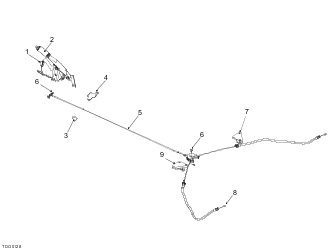
- Parking brake switch
- Parking brake lever
- Guide plate
- Guide plate
- Primary parking brake cable
- Clevis pin
- RH mount
- Secondary parking brake cable
- LH mount
The parking brake is bolted to the passenger seat frame using three ‘patch lock’ type bolts. A conventional thumb operated pawl and ratchet release button is incorporated for locking and unlocking the lever. A parking brake switch is fitted to the lever, secured with two screws.
A single cable is attached to the lever and extends from the rear of the lever under the vehicle to a compensator. The cable is attached at either end using a clevis pin and an R-clip. A second, longer cable is attached to the parking brake mechanism on each rear caliper. The cable passes through an outer cable section between the caliper and brackets on the rear crossmember and also through the compensator. The outer cable section on each side is secured to the front of the lower wishbone using two lugs. Cable adjustments can be made at the threaded section of the outer cable where it passes through the bracket on the LH side of the rear crossmember.
Each rear caliper contains a self-adjusting mechanical link to the rear of the caliper pistons which are pushed out to apply the brake pads to the rear discs when the parking brake is operated.