Motor - Transmission Split
FRT No: 40012101
Remove
- Remove lower shroud from motor
(refer to procedure).
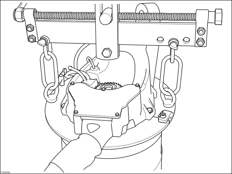
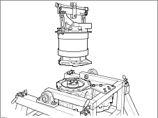
- Fit motor lifting clamp 1001030 to motor.

- Attach a lifting hoist to the motor lifting clamp and raise hoist to remove any slack from the chains.
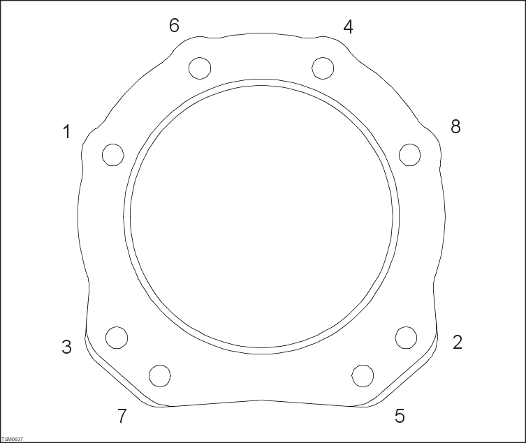
- Working in the sequence shown, remove bolts, washers and insulator bushings (x8) securing motor to transmission.
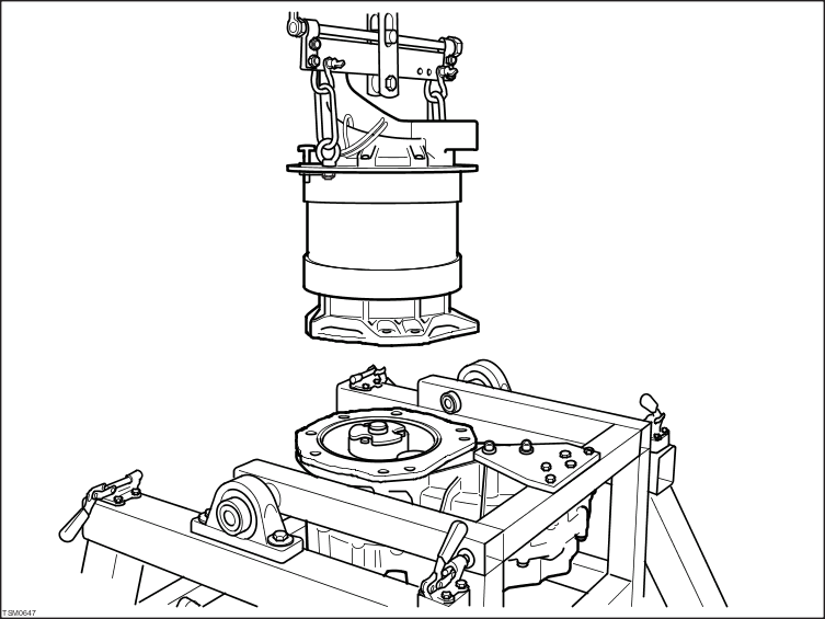
- Slowly raise the lifting hoist to release motor from drive coupler and separate from transmission.
- Position motor aside.
Installation
- Installation procedure is reverse of removal except for the following.
 | CAUTION: Clean and inspect the insulator ring and bushings for signs of damage. Replace any component that shows signs of damage. Under no circumstances should a damaged insulator ring or bushings be used. |
- Clean splines on motor output shaft and apply recommended grease.
- Lower motor onto transmission and engage output shaft with drive coupler.
| CAUTION: The output shaft should locate smoothly with the drive coupler. If resistance is felt, it may be necessary to rotate the motor shaft using the motor encoder wheel to align the splines. Never force the output shaft into the drive coupler. |
- Ensure motor is correctly located on insulator ring before installing the insulator bushes, bolts and washers.
| CAUTION: Do not tighten bolts at this point. |
NOTE: When installing, apply Loctite® 242® thread locking compound to bolt/screw threads.
- Working in the same sequence as used during the remove procedure, tighten the bolts to a torque of 12 Nm.
- Repeat the same sequence and tighten the bolts to a torque of 25 Nm.
- Check that motor and transmission shafts rotate freely by rotating the motor encoder wheel.